You’ll need about 15‑20 GPM per residential zone, which comes from adding the flow of every active head using the 5,940 × nozzle‑size constant at your design pressure. First, total each head’s GPM, then verify your pump can supply that flow without dropping below the manufacturer’s pressure range. Check pipe size with a flow‑size table and calculate friction loss to keep velocity between 6‑18 ft/s. A quick bucket test or flow‑meter reading will confirm real‑world numbers, and the next steps will show you how to fine‑tune pressure and nozzle selection.
How to Calculate the Exact GPM Your Sprinklers Need
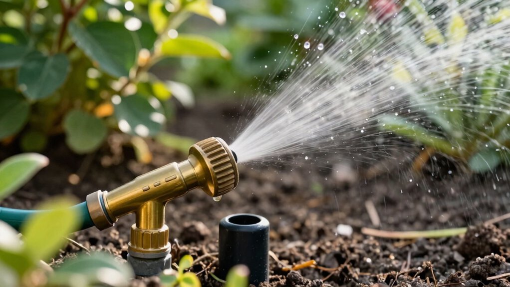
You can pinpoint the exact GPM your sprinklers need by timing how long it takes a five‑gallon bucket to fill under full faucet flow, then applying the simple conversion 5 ÷ seconds × 60. Record the seconds, divide five gallons by that number, multiply by sixty, and you have a reliable flow metric for irrigation system design. A flow meter gauge attached to the hose bib offers a direct readout, confirming bucket test data and reducing timing error. Use the resulting GPM to calculate zone head capacity: divide total GPM by the per‑head demand to guarantee each sprinkler in your residential sprinkler layout receives the correct PSI. This data‑driven method yields precise, repeatable results. The proper pipe size ensures efficient water delivery and protects system performance. Selecting a hose with an appropriate pressure rating helps prevent ruptures and maintains consistent flow under high‑pressure conditions. Understanding hose diameter impact on flow can further fine‑tune system efficiency. Most residential hoses operate effectively between 40 and 80 psi, making optimal pressure range a key factor for consistent sprinkler performance.

360° Rotatable Panel for Easy Reading: The display swivels a full 360 degrees to fit any installation position, allowing you to read data easily without bending or twisting. It works perfectly with faucets, hoses, sprinklers and nozzles, providing a comfortable and convenient viewing experience for all your outdoor watering tasks.

DISCOVER THE ONLY WATER PRESSURE GAUGE KIT YOU WILL EVER NEED. High Quality Glycerin Filled, 0 to 14 Bar, Standard 3/4 GHT (Garden Hose Thread) for all standard outdoor Patio Fixtures, RV Lines, Garden Hoses, Spigots, Faucets And Washing Machine Outlets, Plus 5 Adapters so you can measure in multiple possible settings and locations.

SIZE: 2-1/2"dial size, 3/4"NPT solid brass gate valve,3/4" hose male ,compatible with all us water sources.
How to Choose the Right Nozzle Size for Your Desired Flow and Pressure
Because the flow you need is tied directly to both pressure and nozzle geometry, start by converting your target GPM into the required nozzle size using the 5,940 constant (GPM = 5940 × (Pressure × Area) ÷ Speed). Look up the catalog column for spray pattern characteristics that match your coverage angle, then locate the nozzle ID whose gpm column aligns with your calculated value at the midpoint of its pressure range. For example, a 0.4 gpm target at 40 psi corresponds to XRC8004 or XRC11004, both listed as 110‑04 (110° fan, 0.4 gpm). Verify the pressure flow relationships: higher psi raises flow and alters droplet size, so stay within the manufacturer’s recommended range. If the exact size isn’t available, adjust travel speed or select a nearby size with comparable spray quality. Full circle rotors require twice the flow rate of half‑circle rotors. Selecting the proper nozzle shape ensures optimal distribution and minimizes overspray. Understanding sprinkler pressure helps predict how changes in water pressure will affect both flow rate and spray distance.

What you will get: you will receive 10 pieces variable arc nozzles, enough for your replacements or share with friends and neighbors.

【TECHNICAL SPECIFICATIONS】Interface Inner Diameter: 0.24" (6mm) – fits most standard backpack sprayer; Max Outer Diameter: 0.59" (15mm); Height: 0.43" (11mm); Orifice Size: 0.4mm (also available in 0.15, 0.2, 0.3, 0.5 & 0.6mm – check our other listings)

Package Including: You will receive 10pcs 110 Degree Flat Fan Spray Tips.
Determining Pipe Size Based on Desired GPM and Distance
A 1‑inch pipe can handle about 38 GPM at 40 psi, but once you need higher flow or longer runs you must increase the diameter to keep friction loss low and maintain pressure. First, total the simultaneous GPM demand of your sprinkler system complexity, then locate the corresponding flow capacity in the pipe‑size table. For a 50‑foot run at 40 psi, a 1‑1/4‑inch pipe delivers up to 68 GPM, while a 1‑1/2‑inch pipe reaches 110 GPM, so choose the smallest size that exceeds your calculated head loss after accounting for pipe length, roughness, and material selection. Use the Moody Chart or Swamee‑Jain equation to compute friction loss, round up to the nearest standard diameter, and verify that velocity stays within 6‑18 ft/s. This method guarantees adequate pressure at the farthest sprinkler while minimizing excess cost. The Darcy‑Weisbach equation provides a precise relationship between head loss, flow rate, and pipe diameter. Properly accounting for system head ensures the pump can meet peak demand without excessive energy use. The nozzle’s conversion of pressure energy into kinetic energy follows Bernoulli’s principle and the continuity equation. Understanding sprinkler pressure range helps select appropriate nozzle sizes for optimal coverage.

SIZE SPECIFICATION: 2 Inch white PVC pipe coupling with socket x socket connection design for secure pipe joining

Package contains: 2pcs 1-1/2inch white PVC fittings elbow 90 Degree 2-Way slip socket adapter connectors to meet your replacement needs

Package contains: 2pcs 1-1/2inch white PVC pipe slip socket fitting adapter connectors to meet your replacement needs
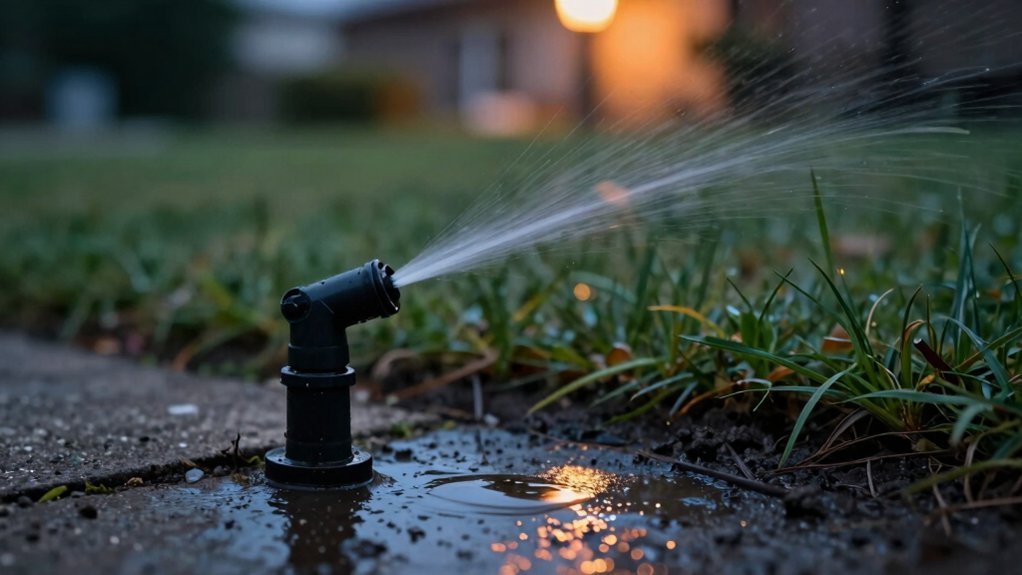
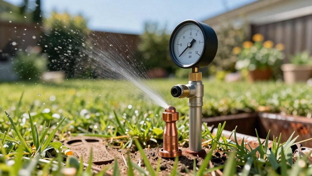
Using a Bucket Test or Flow Meter to Verify Real‑World GPM
After sizing the pipe, you need to verify the actual flow your system delivers. Use a bucket test for measuring gpm accuracy: place a 5‑gallon bucket under the fully opened hose bib, start a timer, and stop it when the bucket hits the 5‑gallon line. Divide 5 gallons by the seconds recorded, then multiply by 60. Example: 5 ÷ 19 s = 0.263 × 60 = 15.8 gpm raw; round down after applying a 20 % loss factor (×0.8) for pipe friction. For faster results, attach a flow‑meter gauge directly to the bib; it reads gpm at the test pressure, eliminating manual calculation. Both methods reinforce your understanding of natural water flow and validate the system meets design specifications. The bucket test also helps determine the available water at the source. Understanding the municipal supply pressure is essential for accurate measurements. Proper pump selection also depends on whether the site’s elevation change exceeds the static head limits of the existing water pressure. Consider hose diameter when linking multiple hoses to minimize pressure loss.

The pure brass inlet and outlet metal thread are heavy duty and enhance durability. No hassle from frequently installs and uninstalls from hose/faucet.

Precision Dual-Scale with Peak Memory: This pressure meter measures 0-200 PSI/0-14 Bar with ±2-1-2% accuracy (ASME B40.1 Grade A). Red max pointer tracks and retains peak pressure spikes, easily reset for monitoring faucets, spigots, or hydraulic systems.

DURABILITY & OUTSTANDING:Water flow meter has pure brass inlet and outlet with metal thread, which will not rust or wear out and is more durable and long-lasting
Scaling Zones – Realistic GPM per Zone for Typical Residential Systems
Typical residential sprinkler zones deliver roughly 15–16 gpm, a figure that stems directly from the combined flow of the heads in each zone and the pipe‑size limits of most homes. You calculate realistic zone GPM by summing each head’s flow, using manufacturer data for rotor (0.12–0.32 gpm) and spray heads, and confirming pipe capacity—1‑inch lines cap near 15 gpm. Verify manufacturer data against static pressure readings; 30 psi yields even distribution, while higher pressure can support more heads without compromising flow. To maximize zone capacity, select the largest feasible pipe, limit heads to 5–6 rotors or 8–10 sprays per zone, and guarantee total system flow exceeds the zone sum. This disciplined approach secures each zone operates within the 15–16 gpm envelope. The Dynamic pressure losses from friction and fittings must also be accounted for to ensure adequate flow. The water source must maintain sufficient pressure to sustain the calculated zone flow. Properly grouping plants by sun exposure helps balance water needs across zones. Pipe diameter directly influences allowable flow per zone.
Interpreting Pump Curves for GPM‑Pressure Planning
Ever wondered how to translate a pump’s curve into the exact GPM and pressure your sprinkler system needs? Start by reading pump curves: the X‑axis shows GPM, the Y‑axis shows TDH in feet. Locate the shaded usable range, then overlay your system curve, which rises with flow due to friction. The intersection point reveals the duty point—your actual GPM and head. Verify that this point falls near the best efficiency point (BEP) for ideal horsepower and NPSH margin. Use the efficiency lines to gauge power consumption, and check the NPSHr curve at the same flow to prevent cavitation from occurring. By mastering reading pump curves and understanding system curves, you can size the pump precisely for sprinkler pressure planning. Some sprinkler valves incorporate built‑in pressure regulators to maintain consistent flow despite varying system pressure. Understanding the solenoid operation helps ensure the valve opens and closes reliably when the controller signals a change. A properly sized pressure tank can also smooth out pressure fluctuations and reduce pump wear.
Fix Low Pressure and Over‑Misting: Common Mistakes & Solutions
If you’re seeing weak spray or a fine mist instead of a solid stream, the culprit is usually low pressure, a clogged head, or an improperly set regulator. Start by measuring PSI at the main line; values below 30 PSI flag a pressure imbalance. Check the supply valve for partial closure, then inspect each head for debris, cracks, or overgrown vegetation that can jam the nozzle. Tighten loose valve connections and replace worn gaskets to stop leaks. Verify the backflow preventer is fully open and free of blockages. When multiple zones run together, pressure drops sharply—schedule zones sequentially or add a pressure regulator to balance flow. Finally, confirm regulator settings match the manufacturer’s 30‑50 PSI range, correcting any deviation to eliminate over‑misting. Sprinkler head may need to be raised if vegetation has grown above it. Regularly clean and replace worn seals to prevent mineral buildup and corrosion. Debris buildup can also cause the nozzle to stick, reducing spray efficiency. Ensure the main supply line is free of air bubbles which can cause erratic pressure fluctuations.
100% pressure tested, to ensure quality and performance

【Lead-Free Brass】: Compare to plastic, lead-free brass is not only durable and safe construction, but also water healthy drinking.

Senninger irrigation water pressure regulators maintain a constant preset outlet pressure with varying inlet pressures, which alleviates pressure differences that can cause an applicator’s area of coverage to change.
Quick Reference: GPM, PSI, Nozzle Size & Coverage
When you size a sprinkler system, the key to uniform coverage is matching GPM, PSI, and nozzle size so the flow stays within the zone’s capacity—typically 16‑18 GPM total. Use a quick reference table: a full‑circle rotor at 45 PSI draws 6‑8 GPM, a half‑circle 3‑4 GPM, and a quarter‑circle 1.5‑2 GPM. Sum the heads to stay ≤18 GPM. Matching nozzle flow to pressure is critical—40‑60 PSI raises application rates ~14 % across all sizes, while 45 PSI is ideal for residential rotors. Choose standardized orifices (e.g., 3/32″ = 0.4 GPM at 40 PSI) and keep lateral spacing consistent for Uniform precipitation coverage. Adjust nozzle size or PSI if the total exceeds zone capacity, and verify head‑to‑head overlap for even distribution.