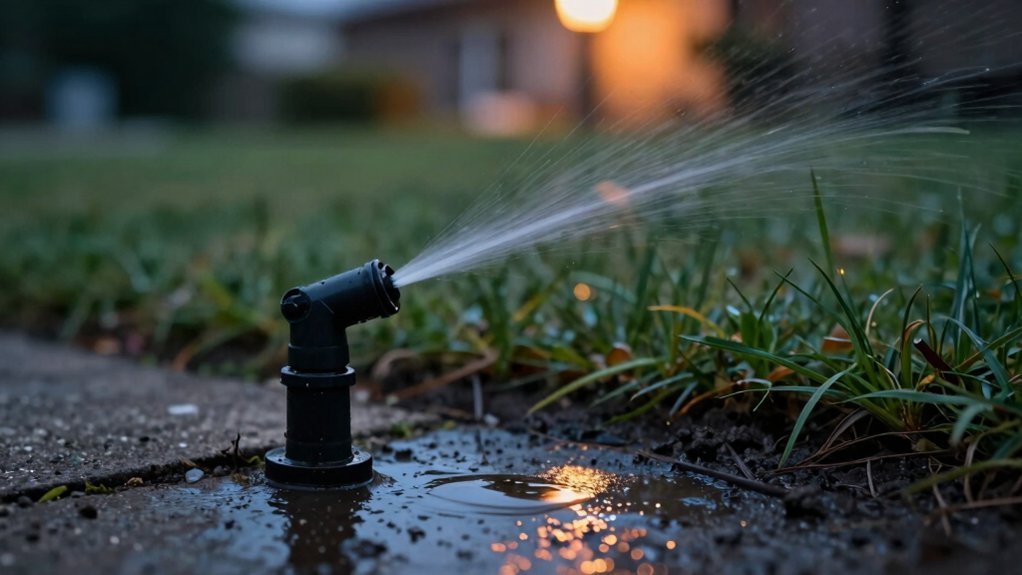
You’ll usually see only one zone fire at a time; if all sprinklers turn on together it means something’s wrong with pressure, valves, or programming. Overloaded pressure, a stuck or open isolation valve, or a faulty master‑valve wiring can force every circuit to activate. Likewise, overlapping schedules or extra programs in the controller can trigger simultaneous zones. Low water pressure also hampers proper valve isolation, making multi‑zone run‑on more likely. Fixing these issues will restore single‑zone operation, and the next sections show exactly how.
Why Sprinkler Zones Activate Together (and How to Stop It)
When multiple sprinkler zones fire together, the controller is fundamentally sending power to more than one solenoid at once, which overloads the system’s pressure, wiring, and electrical capacity. This simultaneous activation forces each valve to work harder, stretching its flow capacity and creating pressure surges that exceed design limits. The excess demand triggers solenoid burnout as voltage drops across longer runs, while the heightened system pressure demands accelerate internal wear, leading to premature leaks. You’ll also see uneven distribution: water pressure splits among zones, dropping below the minimum PSI needed for reliable opening. The result is a cascade of failures—valve strain, pipe stress, and reduced sprinkler efficiency—until you isolate zones or rewire to prevent concurrent operation. A malfunctioning valve can stay open, causing simultaneous zone activation and excessive water waste. Regular inspection can catch faulty valves before they cause leaks. Improper seal installation can also contribute to early valve failure. Selecting a solenoid with the correct voltage rating for your controller prevents electrical overload and extends valve life.
Common Controller Programming Mistakes That Cause Multi‑Zone Running
The simultaneous valve activation described earlier often stems from how the controller’s program logic is set up. You’ll find extra programs (A, B, C) still enabled on the LCD; tiny digits flag unintended schedules. Remove them with the PGM button, then verify each program’s start‑time list. Up to four start times per program can stack, so advance past midnight with the “+” key to delete stray entries. Avoid assigning two zones to run at the same minute; overlapping zones trigger P ERR and force the master valve open, creating multi‑zone flow. Faulty rain sensors or SmartPort wiring also masquerade as programming errors, so bypass or rewire them. Finally, incorporate seasonal irrigation adjustments and monitor stagnant water quality, because poor water can mask timing faults and exacerbate zone overlap. Check voltage at the common and zone terminals before testing each zone. Regularly inspect the timer’s battery health, as a low‑power condition can cause erratic scheduling and intermittent clicks in the control panel. Locate the main water valve before troubleshooting to ensure you can quickly shut off flow if needed.

Upgrade Existing Controllers with Wireless Access - Transform compatible irrigation controllers into connected systems with this 2nd generation WiFi accessory. Quick Pair technology enables fast setup, while sprinkler controller connectivity and wireless irrigation management help simplify daily operation.

Complete 42-piece Drip irrigation kit eliminates watering by hand
[Professional 172FT High-Flow System] This comprehensive drip irrigation system kit features 172FT of premium tubing, including a 132FT 1/2" (12mm) high-flow mainline. Compared to standard 1/4" hoses, our thickened 12mm pipe ensures consistent water pressure throughout the entire automatic watering system, delivering strong flow to every nozzle without pressure drops.
Low Water Pressure: How It Prevents Proper Valve Isolation
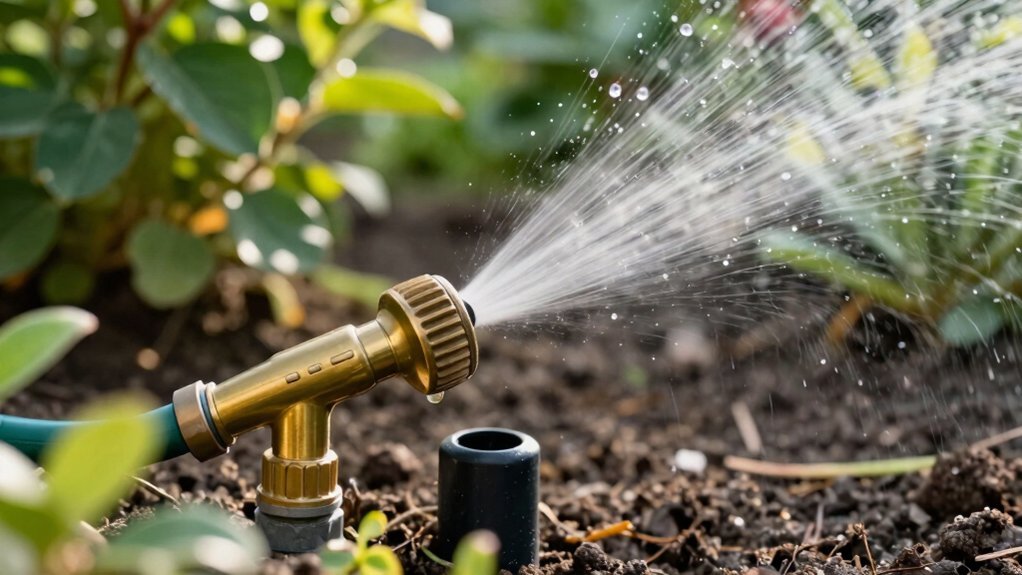
If the water pressure is low, the isolation valve‘s smaller bore will choke the flow, preventing the valve from fully closing off a zone. You’ll notice valve performance degradation because the reduced pressure limits the valve’s ability to seal, and flow impedance mechanisms become dominant. Smaller bores restrict the water rate, especially when flexi hoses add extra constriction. Replacing those hoses with larger‑bore alternatives or switching to full‑port ball valves cuts the impedance, restoring pressure. During installation, tighten valves just enough to avoid additional restriction and guarantee the main stopcock stays fully open. Proper housing of exposed stems prevents leaks that would further lower pressure. By managing these variables, you maintain adequate isolation without sacrificing system flow. Removing isolation valves also helps increase overall water pressure. Accurate sprinkler head flow calculations are essential for sizing the system and preventing simultaneous overload. The hose’s flexible tubing allows Bernoulli’s principle to govern flow speed and pressure changes along its length. Using a longer hose can cause pressure loss that reduces effective cleaning power.

Packing including: 1 Pack Brass Shut Off Valve with 2 Pressure Washers and 1 Pack Sealing Tape.

FULL PORT DESIGN: Heavy-duty full port ball valve features a 3/4 in. IPS connection on each end to support maximum flow and reduce pressure drop

Body & Ball Type:Full Port, Low Operation Torque,304 Stainless Steel
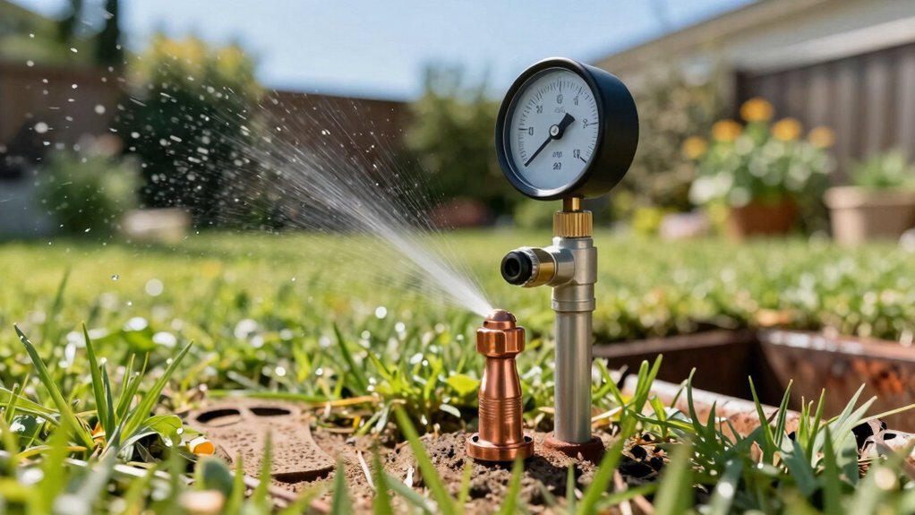
How to Boost Water Pressure for Reliable Zone Switching
Low water pressure stalls zone switching because the valve never reaches a firm seal, so the next zone can’t be isolated reliably. To fix this, first verify gauge readings and adjust the pressure regulator bolt clockwise in 1‑psi increments, never exceeding 75 psi. Clear any clogged pipe sections and replace undersized runs to reduce friction loss; larger‑diameter lines keep flow steady. Install a booster pump if source pressure is low, employing booster pump strategies like a constant‑pressure centrifugal unit with an automatic thermal switch to avoid cycling. Guarantee the backflow preventer function remains intact; a properly sized preventer prevents reverse flow without throttling pressure. Finally, set the pressure tank pre‑charge 2 psi below pump cut‑in (≈28 psi) and eliminate leaks for consistent zone isolation. Elevation changes can pressure by 0.433 psi per foot of vertical drop. Properly calculating the required pump capacity involves determining the total system head and flow rate (GPM) based on sprinkler type and pipe layout. Assessing pump necessity ensures the system meets performance standards. Modern sprinkler valves often incorporate built‑in pressure regulators to maintain consistent flow across varying pressures.

【Wide Applications】TDRFORCE 540E is your ideal RV water pump electric , automatic inline water pressure booster pump for home. With self priming function, the pump transfer fresh water with 110v ac can act as a freshwater washdown pump for boats, marine water pump, diaphragm pump and work for garden hose booster.

Automatically Electric Control: This shallow water pump has a powerful 1HP motor, providing 1380 GPH max flow and 145 ft max head. The jet pump can boost home water pressure with an electronic controller to ensure automatic work and prevent dry running. Whether you're in the shower or using the faucet, this pressure booster will keep your water pressure going strong.

Optimal Suction and Discharge: MAX.Q 4250 GPH, Max Head 108 ft, With a 2" NPT suction and a 1-1/2" NPT discharge, the jet pump offers optimal water flow for various irrigation requirements, ensuring your lawn remains lush and green
Winterization Valves Left Open: A Hidden Multi‑Zone Trigger
When you leave winterization valves open, pressure can bypass the intended isolation points, causing multiple zones to receive water simultaneously during the next start‑up. This creates an unintended zone grouping that defeats the controller’s schedule. The open valve forms a low‑resistance path, allowing water to flow into adjacent lines before the primary zone valve opens. As a result, the controller registers a single pressure surge, triggering simultaneous valve actuation across several zones. You can verify the fault by monitoring pressure different during startup; a single spike indicates a shared pathway. To prevent this, close each winterization valve after blow‑out, confirm isolation with a pressure gauge, and test each zone independently before re‑activating the system. Skipping winterization can lead to substantial damage to the irrigation system. Properly draining the system with compressed air also helps prevent freeze damage. Water in exposed pipes can solidify when temperatures drop below 20 °F (‑6 °C), increasing the risk of burst lines if not properly insulated. Proper insulation protects the system from freeze‑induced cracks.
Diagnosing Stuck or Manually Open Valves in Your Lawn System
Identifying a stuck or manually open valve starts with a systematic visual and tactile inspection; you’ll first shut off the main water supply, then remove the valve bonnet to expose the diaphragm, solenoid, and bleed screw. Next, examine the rubber diaphragm for sand, grit, or tears that could impede closure, and verify the manual bleed screw is seated, not missing. Proceed to solenoid diagnostics: confirm the O‑ring seal, test plunger movement, and check for a spring or seat defect. If mechanical parts appear sound, use a multimeter to detect solenoid opens or shorts. Finally, trace the controller wiring to the valve box, note any continuous current, and document brand, model, and wear before deciding whether to rebuild or replace the valve. Check the solenoid for proper activation by listening for a faint hum when the controller is on. Understanding the solenoid coil function helps diagnose why a valve may stay open despite no controller signal. Irregular watering can indicate a failing solenoid that is not fully closing. Most sprinkler solenoids are polarity‑agnostic and will operate correctly regardless of wire orientation.

Replacement solenoid for Rain Bird APAS, ASVF, ECV, CP, CPF model valves

Captive hex plunger feature

For replacing solenoids which open and close 24V automatic irrigation valves
Testing One Zone at a Time to Find Wiring Problems
How can you pinpoint a wiring fault without dismantling the entire system? Start by isolating a single zone on the controller. Set the multimeter to AC volts, attach one lead to the zone terminal and the other to the common wire. A reading near 24 V confirms the controller output; anything lower flags a fault. Next, disconnect the zone and common wires from the controller and switch the meter to ohms. Measure between the two leads; 20–60 Ω indicates healthy wire and solenoid. Values outside that range suggest improper zone wiring or solenoid connection issues. If the reading is high, trace the field wire for breaks; if low, inspect the solenoid for a short. Retest the zone after each repair before moving to the next. Solenoid resistance typically falls within the 20‑60 Ω range. The valve housing often includes a transparent cover that lets you see the internal diaphragm. Regularly inspect the system for uneven watering to catch valve wear early.
Master Valve Wiring Issues That Cause Simultaneous Activation
After you’ve isolated a faulty zone with a multimeter, turn your attention to the master valve wiring, because a mis‑wired master can make every zone fire at once. Examine the controller’s master slot; firmware accepts only one master station, so any extra solenoid wire tied to ports 3 or 4 creates a common wiring fault that triggers simultaneous sprinkler activation. Verify that the common wire runs solely to the master valve before splicing to zone wires; an incorrect splice or uninsulated conductor will short the circuit and energize all zones. Check for open circuits by disconnecting the master wire from the M terminal and observing whether the controller skips cycles. Guarantee the master valve is installed, enabled in settings, and that no parallel‑station feature is unintentionally active. Ensure the dedicated wire resistance falls within the 20‑60 ohm range to confirm proper connection. Consider that many modern controllers operate on low‑voltage DC for improved energy efficiency and compatibility with battery or solar backup systems.

【Replaces OE】- 350-0025 12143296 12121299 74425NC, 51870EC, 77995A, 74425S
Premium Materials: The shell of this headlight connector socket is made of durable nylon plastic, which is tough and heat-resistant, won't melt and is not easy to break, and the internal wires are high-conductivity copper wires, which ensures a strong current-carrying capacity and stable power transmission.

Heavy-duty Harness: 16 AWG stranded wire, up to 180W load capacity. The harness is protected by power relay and inline blade fuse as the first Line of defense against overcurrent and short circuits
Final Checklist: Ensure Only One Zone Runs at a Time
A concise final checklist confirms that each zone operates independently before preventing simultaneous activation. Verify controller programming practices: assign one program per watering need, set sequential stations, and lock start times to avoid overlap. Confirm each zone’s run time matches its pressure capacity; a 5 GPM pump should serve only one zone at a time. Inspect solenoids and valves for debris that could hold a zone open, and test zones individually after cleaning. Guarantee no pigtailing bypasses the controller’s single‑zone limit. Check that any new zones have updated programming and that pump capacity matches the expanded load. Review ordinances for watering windows and adjust schedules accordingly. Follow these steps to maintain ideal pressure and avoid wasted water. The controller’s dark blue area on the face plate displays the set program start times, providing a quick visual reference for program timing.