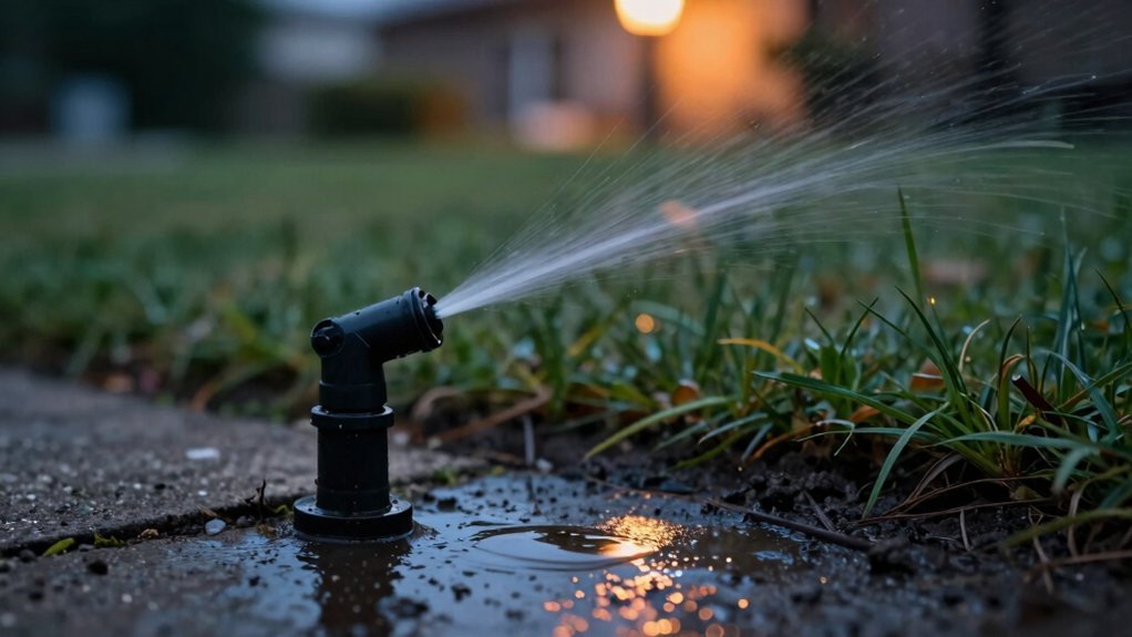
You’ll find that every modern residential sprinkler zone relies on a solenoid‑actuated valve to start and stop water flow. The controller sends a 24 VAC pulse, lifting a spring‑loaded plunger, dropping pressure in the bonnet chamber, and allowing the diaphragm to open the main flow. When the pulse ends, the spring reseats the diaphragm and seals the dump port. This fast, reliable on‑off action is why solenoids dominate zone control, and the next sections explain how valve type, pressure, and diagnostics shape your system.
How Solenoid Valves Control Your Irrigation Zones
When you install a solenoid valve, it becomes the gatekeeper for each irrigation zone, opening only when the controller sends a 24 VAC signal and staying closed otherwise. Choose an energy efficient valve design that draws 150–400 mA so the system runs on minimal power. Wire each zone’s solenoid to a dedicated controller output; the controller’s schedule sends the 24 VAC pulse at the programmed start time, then cuts power to close the valve. Guarantee integration with smart controllers that can read rain, soil‑moisture, and flow sensors, allowing automatic cancellation of the pulse when conditions dictate. Verify that the valve’s pilot‑operated diaphragm handles the 12–16 Bar supply pressure, keeping pressure balanced across sprinklers and drip emitters. Adjust flow‑control settings per zone to match plant needs, and confirm that the master valve isolates the main line for maintenance. The ball valve can be manually opened to allow water to fill the bonnet’s chamber above the diaphragm. The compact housing often features a transparent cover that reveals the internal diaphragm. Understanding pressure‑balanced operation helps prevent uneven watering when zone pressures vary. Selecting a compatible voltage rating ensures the solenoid will function reliably with your controller’s output.

For replacing solenoids which open and close 24V automatic irrigation valves

24VAC Standard Voltage for Irrigation Systems: Designed for 24VAC sprinkler and irrigation control systems, delivering stable and responsive valve operation. Ideal replacement solenoid for residential and commercial irrigation valves
How a Solenoid Valve Works in a Typical Residential System
Your controller’s 24 VAC pulse triggers the solenoid, which then lifts the spring‑loaded plunger and lets water pressure in the bonnet chamber drop, releasing the diaphragm from its seat and opening the main flow to the zone. When the plunger retracts, water escapes through the dump port, equalizing pressure and allowing the lower chamber to push the diaphragm upward. As the diaphragm lifts, the valve seat clears and water rushes into the irrigation line. When the pulse ends, the spring forces the plunger back, sealing the dump port; the bonnet chamber refills, pressure on the diaphragm’s top side rises, and the diaphragm reseats, cutting flow. Follow the maintenance requirements by inspecting the pilot flow filter and cleaning the diaphragm seat to prevent cross contamination concerns. Regularly verify coil resistance and spring tension to guarantee reliable actuation. Low‑voltage power supplies often include battery backup to maintain operation during outages. Tracing the wiring diagram can help you locate the solenoid quickly. Some sprinkler systems also incorporate a pressure regulator to protect the valve from excessive water pressure.
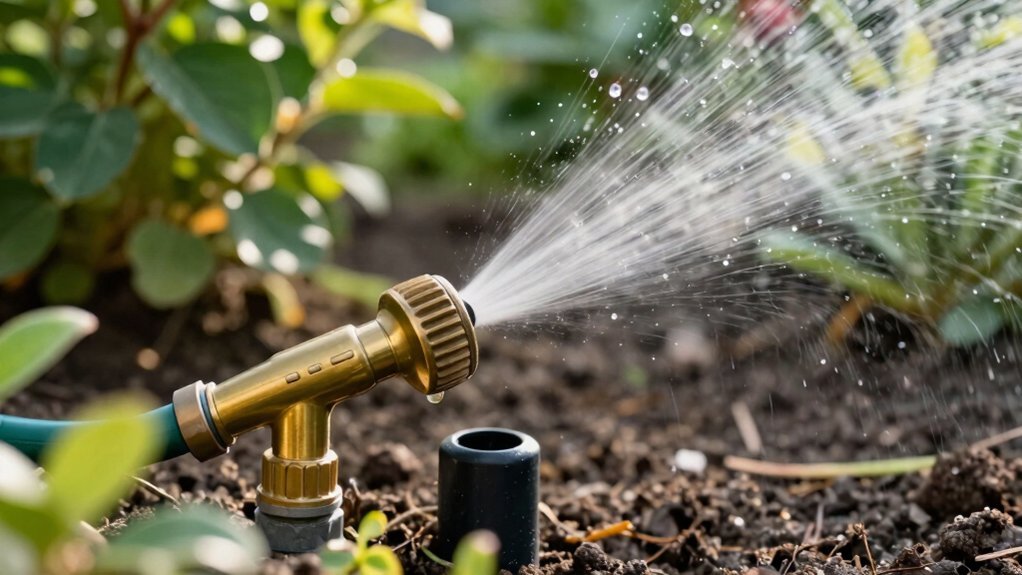
Which Valve Type Fits Each Irrigation Zone (Solenoid vs. Manual/Ball)?
Choosing the right valve for each irrigation zone hinges on three factors: automation demand, fluid cleanliness, and flow‑rate requirements. If you need timed watering, remote activation, or sensor integration, you’re deciding manual vs automated valve and should select a solenoid. Solenoids deliver fast on‑off response, work best with clean water, and handle frequent cycling in residential lawns or commercial fields. For zones with high pressure, large pipe diameters, or particulate‑laden water, a ball valve optimizes flow and durability; it tolerates debris and provides higher flow rates. Small garden sections that never require timers benefit from a quarter‑turn manual valve, which minimizes cost and maintenance. Match each zone’s automation need, water quality, and flow demand to the appropriate valve type to achieve reliable, efficient irrigation. Motorized ball valves require power only when actuating and thus reduce energy consumption during prolonged operation. Correct coil voltage is essential to prevent overheating and ensure reliable actuation. Regular valve inspections can catch low pressure early before it damages the system. Polarity‑agnostic solenoids typically work with either wiring orientation, simplifying installation.
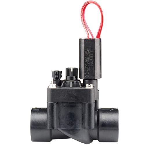
BUILT-IN FLOW CONTROL FOR ZONE PRECISION: Control water flow to each irrigation zone and prevent overwatering. Helps improve system efficiency, reduce misting, and support healthier landscapes.

Wide Compatibility: this irrigation valve solenoid compatible with Hunter PGV & ICV irrigation valves, which ensures reliable performance in automatic lawn sprinkler systems and garden irrigation setups

For controlling the flow of water in sprinkler or drip irrigation zones; 24 VAC solenoid includes manual actuation with a twist of the solenoid
When to Use Shared or Hybrid Solenoid Valve Setups
After weighing automation needs, water cleanliness, and flow rates, you’ll notice that many zones share similar timing and pressure profiles, making a shared or hybrid solenoid arrangement worthwhile. Use modular manifold configurations when you need to expand zones without rewiring; each manifold can host several valves that tie into a single station wire via waterproof joiners. Adopt single wire wiring topologies by stripping solenoid leads into hook shapes and linking color‑coded station wires sequentially, preserving access for three‑plus valves. For battery‑ or solar‑powered controllers, integrate a latching solenoid with a standard coil, energizing briefly to hold position and saving power. Test continuity after each join, avoid blocking the common return path, and program the controller with fewer dedicated outputs to reduce cost and simplify maintenance. Ensure valve wires are of sufficient length for future needs. Low‑voltage control circuits can also be incorporated to monitor valve status and trigger alarms when necessary. Irregular watering often indicates a failing solenoid or voltage drop. Consider checking the main water valve location when searching for the control box to ensure proper access.

OE Part Number: L30118741 ,L301-18-741,L80118741 ,L801-18-741,1S7G9J559BB ,1S7-9J559-BB,1S7Z9J559BA , 1S7Z-9J559-BA, 3S4Z9J559AA , 3S4Z-9J559-AA

【High-Efficiency Performance】This VIAS variable intake control system solenoid valve is precisely manufactured with high-quality materials, ensuring stable performance and high sensitivity. It effectively improves engine power output and efficiency. Designed specifically to address the P1800 fault code, it is a direct replacement and requires no programming or calibration

Fit for select 2002-2017 modles. More in description.
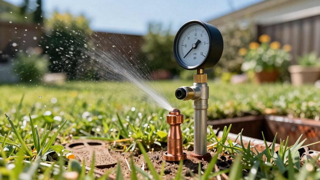
How Solenoid Valve Pressure and Flow Affect Zone Performance
The pressure at which a solenoid valve operates and the flow it passes directly dictate how consistently a zone will irrigate. First, verify that each valve’s rated pressure exceeds the system’s maximum working pressure; a valve rated for 75 PSI will fail if the line spikes above 4000 psi. Next, calculate zone flow by summing emitter rates—200 half‑gallon drippers equal 100 GPH—and guarantee the valve’s flow coefficient matches this demand. If you notice slow streams or pop‑up failures, raise dynamic pressure above 35 PSI and perform valve pressure adjustments. Use regulating zone flows to balance distribution, installing pressure regulators upstream or at each valve outlet. This maintains uniform spray patterns, prevents runoff, and optimizes water use across all zones. Pressure regulators are crucial for efficient irrigation systems. Adding a pressure tank can reduce pump cycling and protect the system from water hammer. PVC Schedule 40 is not recommended for high‑pressure sprinkler lines because it lacks the necessary pressure rating. Selecting the proper pump size ensures the system can meet the required flow and pressure without excessive cycling.
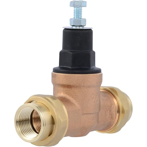
CASH ACME WATER PRESSURE REGULATOR: The Cash Acme Direct Pressure Regulating Valve (PRV) features a half cartridge design which offers the added benefit of direct access to the pressure adjusting screw and the performance of a high-end cartridge valve at the cost of a traditional regulator; regulates downstream pressure in commercial and residential water applications
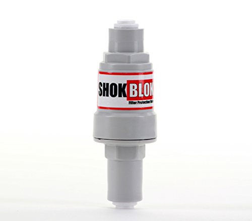
60 PSI Limiting Protection Valve

CASH ACME WATER PRESSURE REGULATOR: The Cash Acme Direct Pressure Regulating Valve (PRV)is designed to reduce incoming water pressure as well as prevent pressure surges to protect plumbing components. The valve offers simplicity and maintenance benefits of a cartridge-based valve while preserving the construction of a traditional regulator with a separate spring chamber and adjusting screw
Diagnosing Common Solenoid Zone Failures
When a zone won’t activate or runs continuously, start by checking the valve’s mechanical and electrical health, because most failures stem from stuck or burned‑out solenoids, debris‑clogged diaphragms, or broken low‑voltage wiring. First, measure solenoid resistance; values outside 20‑60 Ω indicate a short circuit or coil burnout. Open the valve box, inspect wire nuts, and verify that corroded or rodent‑damaged splices are tight. Use a multimeter to confirm 24 V presence at the coil terminals; intermittent voltage suggests loose connections, which is a common cause of diagnosing intermittent valve failures. Flush the valve to remove sediment, then test diaphragm movement manually. Replace burned‑out solenoids and reseal wiring before retesting zone operation. Check the wiring for proper resistance before activating the zone. A step‑by‑step diagram can help visualize the correct wiring layout. Thermostat wire is generally rated for low‑voltage use, but its gauge and insulation may not meet the durability requirements of outdoor irrigation systems. Ensure that any buried sprinkler wire is UV‑resistant and rated for direct burial to prevent moisture intrusion and long‑term degradation.

Replacement solenoid for Rain Bird APAS, ASVF, ECV, CP, CPF model valves

For replacing solenoids which open and close 24V automatic irrigation valves
What’s Next for Smart Irrigation Valves?
Because today’s irrigation systems can already stream soil‑moisture data and weather forecasts, the next generation of smart valves must fuse IoT connectivity, AI‑driven scheduling, and autonomous power sources into a single, self‑optimizing unit. You should select valves that embed edge‑computing chips to preprocess sensor streams, then apply predictive data analytics that combine forecasted evapotranspiration with real‑time moisture readings. Deploy solar‑powered or battery‑operated modules to guarantee irrigation system autonomy in remote fields, eliminating trenching and grid dependence. Integrate high‑performance polymers and pressure‑resistant housings to survive harsh chemistry and terrain. Enable two‑way communication so each valve reports flow, pressure, and clog alerts to a central dashboard, allowing adaptive algorithms to refine schedules and cut water use by up to 50 %. A pump may be necessary when the system pressure falls below the valve’s operating range. Understanding flow dynamics helps engineers size nozzles and pipelines for uniform water distribution.