You’ll find the solenoid in the buried valve box or an above‑ground cover—usually a 10‑inch plastic or metal cap near a house corner, back‑flow preventer, or the first pressurizing sprinkler. Dig a shallow trench over the cap, then place a stethoscope or chatter locator on the ground and pulse the valve at 1 Hz; the characteristic click pinpoints the solenoid. Trace the wire with a locator, confirm red/black connections, and you’ll have it located fast—more details await if you keep going.
Identify Typical Sprinkler Solenoid Placement in Residential Systems
When you install a residential irrigation system, you’ll typically locate the manifolds in easily reachable spots—often in the front yard, backyard, or multiple points that correspond to the zones they serve. You’ll choose manifold accessibility options that keep valves within arm’s reach for maintenance while minimizing pipe runs. Each solenoid attaches directly to its valve body inside the manifold, and the valve box shields the assembly. Solenoid protection levels are met by burying the box underground, sealing splices with grease‑filled connectors, and keeping wiring high above water. The common white wire twists with one solenoid lead per valve, and zone‑specific colored wires connect to the other lead. This arrangement isolates each zone, simplifies troubleshooting, and preserves component durability. Use unions to make future maintenance easier. Understanding the voltage compatibility of a solenoid helps prevent premature failure.

Compatibility: This SOLASSG4 solenoid repair kit replacement for rain bird PEB, PGA, EFB-CP, BPE/BPES and GB Valves, replace 236239. This repair kit is designed to restore the functionality of the solenoid valve in the irrigation system.

Compatible Models: This is a solenoid repair kit replacement for PEB, PGA, EFB-CP, BPE/BPES and GB Valves

Replacement solenoid for Rain Bird APAS, ASVF, ECV, CP, CPF model valves
Spot the Valve Box or Above‑Ground Cover Before Digging for Solenoid Location
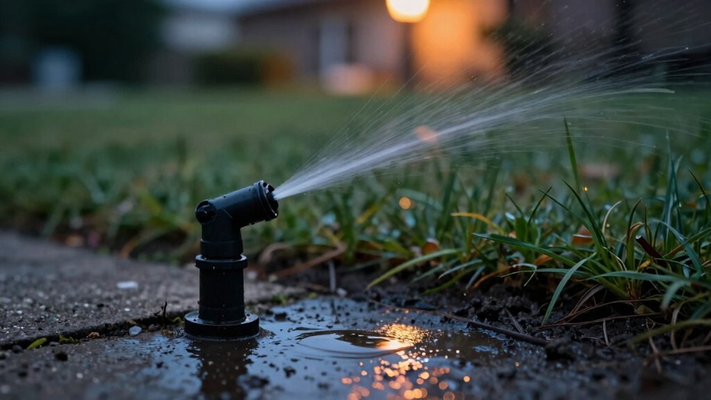
Spot the valve box or above‑ground cover before you start digging, because the shallow, surface‑level lid marks where the solenoid and its wiring lie beneath the soil. Walk the irrigation line and scan for round, 10‑inch plastic or metal caps near house corners, back‑flow preventers, and the first pressurizing sprinklers. These covers sit directly over the buried valve enclosure, so you can pinpoint the solenoid without blind probing. If you encounter unmarked valve boxes, pause and verify their location; digging blindly risks cutting wires or rupturing the solenoid housing. Limit soil sifting to confirmed cover spots, and avoid probing soil dangers by confirming the lid’s presence before you break ground. This method protects the system and speeds up the repair. Use the activator’s chatter mode to generate a clicking sound that helps locate the hidden solenoid. Control box placement is often near the main water valve, making it a useful reference point. Properly mounting valves vertically can improve flow consistency and simplify future maintenance. Understanding low‑voltage power requirements helps ensure the system runs efficiently and safely.
Use a Stethoscope or Chatter Locator to Hear the Solenoid Click
You can pinpoint the solenoid by listening for its characteristic click with a stethoscope or a chatter locator, which amplifies the valve’s activation sound. First, turn off the main water supply, then connect a 24 VAC relay to the valve circuit and select the target zone on the controller. Flip the SPST switch to pulse the solenoid at one hertz. While the valve clicks, place the stethoscope probe directly on the ground surface—this is the ideal stethoscope placement for capturing audible solenoid volume. Walk slowly, listening for rhythmic clicks that increase in intensity as you approach the valve. If you use a chatter locator, replace the controller switch, set the relay to 1 Hz, and follow the same walking pattern, watching the LED blink in sync with the solenoid’s on‑off cycle. This method isolates the click from water flow noise and narrows the search zone quickly. Ensure the transmitter signal is strong enough, above 4 on the meter. Most sprinkler solenoids are polarity‑agnostic and will operate correctly regardless of wiring direction. A failing solenoid often shows irregular watering patterns that can be confirmed by measuring voltage at the valve. Understanding valve spring tension helps prevent premature wear.
Trace the Solenoid Wire With a Locator or Null‑Principle Method
After hearing the solenoid’s click, you can locate the exact wire run by using a tracer or the null‑principle technique. Connect the red lead to the station wire on the controller, disconnect the common wire, and attach the black lead to the transmitter’s black outlet. Clip the ground stake into clean soil away from other grounds, then select direct clip‑on mode and a low frequency for deep paths. Turn the transmitter to, set output to maximum, and walk the receiver over the ground. Watch the signal‑strength bars and listen for the tone; the null point disappears when you pass over the solenoid, and a strong peak appears within a 2‑4‑foot radius. This wire pathway tracing method gives precise wireless signal detection without digging. The Armada Pro900’s ground‑stake improves signal stability in dry soil. Always call 811 before any digging to avoid damaging underground utilities. Excess moisture from a sprinkler leak can cause soil expansion, which may compromise the foundation’s integrity. Using a metal detector can also help identify the metal components of the sprinkler line before you begin tracing.
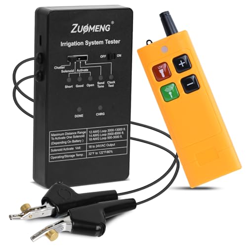
Fast and Accurate Irrigation System Diagnostics: Quickly locate and troubleshoot underground sprinkler system issues with built-in solenoid activation and wire identification functions. Bright LED indicators clearly display voltage, solenoid status, and battery level, reducing repeated testing and improving overall efficiency

PORTABLE IRRIGATION SYSTEM TESTER: The Model 24BK Station Master Pro is a highly portable, battery-operated irrigation system tester, ideal for quick troubleshooting and diagnosing faults in irrigation systems.

PORTABLE IRRIGATION SYSTEM TESTER: The Model 24BK Station Master Pro is a highly portable, battery-operated sprinkler valve locator, ideal for quick troubleshooting and diagnosing faults in irrigation systems.
Follow the Pipe From the Controller to Pinpoint the Solenoid’s Valve
Since the controller marks the system’s origin, start by locating the white PVC mainline that exits it and then walk the pipe toward the irrigation zones, using pacing (≈50 ft per segment) to gauge distance and keeping an eye on sprinkler patterns that reveal the pipe’s direction. As you pace, record pipe measurements and note any changes in terrain that may require you to widen search area. Probe the soil gently every 17 paces; a faint click or resistance often marks a valve box. Follow the mainline past straight sections along fences, then look for lateral branches near corners or field edges. When you encounter a surface cover, confirm it’s a valve box before proceeding to the solenoid’s valve location. Connect the grounding rod to the alligator clip before tracing the wire. The pressure regulator ensures consistent flow throughout the system. A pump may be necessary if the system’s elevation changes exceed the available water pressure limits. Properly sizing the pump involves calculating the required GPM flow based on sprinkler head specifications and layout.
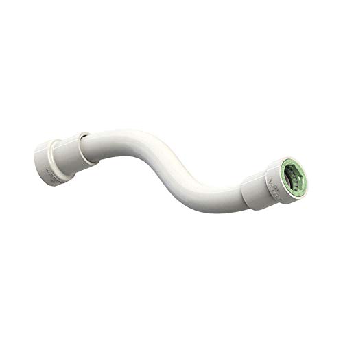
For PVC Pipe Only: Repairs broken or misaligned Schedule 40 PVC pipe in non-constant pressure irrigation lines; not for use with garden hoses, poly pipe, or flexible tubing

Flexible 50ft 1/2" drip irrigation tubing that bends around raised beds, greenhouse staging, and irregular garden layouts without kinking or cracking. At 0.5" ID / 0.65" OD it is compatible with all standard quick-connect irrigation system fittings for fast tool-free assembly. High-quality durable construction supports above-ground and underground installation — ideal mainline for any garden drip irrigation system or vegetable garden watering system.
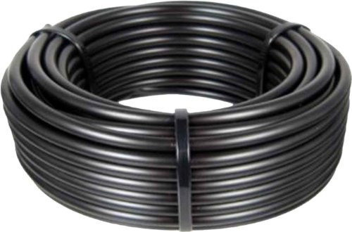
Use with 1/2-Inch barb drip fittings or .620 green end fittings
Locate the Diaphragm Valve Housing the Solenoid
The diaphragm‑valve housing is the cylindrical or bonnet‑shaped enclosure that sits inline with the irrigation lateral, with the solenoid coil mounted on top of the diaphragm assembly. First, expose the valve box and locate the housing’s inlet (port 1) and outlet (port 2) markings; the flow arrow shows direction. Shut off water and de‑energize the coil. Remove the coil by loosening its screw or clip, then unscrew the four cover screws or housing nut to lift the bonnet. Pull the plunger out carefully; you’ll see the O‑ring and diaphragm cartridge. Perform a diaphragm cartridge inspection, checking for tears, debris, or mis‑alignment. After inspection, re‑seat the cartridge, tighten the housing nut to the indexed mark, and reinstall the coil. Maintain a stock of diaphragm repair kits to ensure quick replacement when needed. Verify that the solenoid’s voltage rating matches the controller’s output before reinstalling. Not all zones require a solenoid, as some systems use manual or mechanical valves instead. The valve’s threaded inlet and outlet allow secure connections to the irrigation system.

Replacement diaphragm for Orbit 100-series automatic 3/4-inch. (57100) and 1-inch. (57101) internal bleed valves, except Anti-Siphon.

COMPATIBLE WITH POPULAR HUNTER VALVES: Designed for use with Hunter PGV, SRV, ASV, PRO-ASV, PGV Jar Top, PGV-100G, PGV-101G, PGV-100A, and PGV-101A plastic 3/4" and 1" valves. Ideal for quick replacements without digging or full valve swaps.

Compatible with Rain Bird CP, CPF, DV, DVF, DAS & ASVF valve series. This replacement diaphragm repair kit fits DRKCP/CPF models and is designed to help address valve leaks.
Verify Red/Black Activation Wires and Their Connection Points
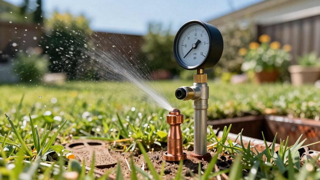
Check the red and black activation wires at the solenoid and at the controller to confirm they’re correctly routed, securely terminated, and delivering the proper voltage. First, locate the red wire on the zone terminal and the black return on the common bus. Use a multimeter to measure 24‑28 V across the pair when the zone is called; any deviation means a loose wire termination or bad terminal connection. Visually inspect each splice; waterproof wire nuts must be tight, and grease caps should seal the joint. If the voltage reads correctly but the solenoid doesn’t click, verify continuity with the controller disconnected. A wire tracer can pinpoint breaks along the pipe run, ensuring the red/black paths remain intact. Turn off the main water supply before starting any wiring checks to prevent accidental spray. Uneven watering may indicate a clogged valve that requires cleaning or replacement. Understanding valve wiring helps troubleshoot issues efficiently. Make sure to verify that the thermostat wire you plan to use meets the low‑voltage requirements for irrigation controllers.
Confirm Solenoid Location Using a 521A/521E Activator
Where exactly is the solenoid? You start by troubleshooting transmitter configuration: connect the red lead to the station wire, the black lead to a ground stake, power the 521A/521E, and set the output to its highest level. Disconnect all controller wires, then use the receiver to evaluate receiver filtration performance. Hold the 521E vertically, tip to the ground, and lower the sensitivity knob until you’re about six inches from the wire path. Walk the probe along the trench; the null will persist until you pass the solenoid, where the signal spikes dramatically. Mark that hot spot, verify the null resumes beyond it, and confirm depth with the 45‑degree indicator. This pinpoint method isolates the underground valve quickly. The device uses magnetic location to trace low voltage AC irrigation wiring beneath the soil. The nozzle’s effect on fluid flow can be explained by Bernoulli’s principle which shows how pressure energy converts to kinetic energy.
Fix Common False Positives From Listening Devices
Many false positives arise when ambient noises or neighboring zones mask the true solenoid click. First, attach a mechanic’s stethoscope to amplify weak solenoid signals while you mute water flow and air hissing. Then, isolate zones one at a time to avoid cross talk from nearby wiring; turn off all other zones and energize only the target. Use a wire tracer set to a narrow detection radius, keeping the receiver directly over the valve box to capture the rhythmic click. Verify power delivery with a chatter locator, ensuring the analog needle reaches level 4 before interpreting any signal. Ground your equipment properly and secure red‑black leads to prevent electromagnetic induction that could masquerade as a solenoid activation. The valve box is typically located near the sprinkler heads for that station.
Document Solenoid Location for Future Maintenance and Repairs
You’ll want to record each valve box’s exact spot as soon as you locate it, noting the zone number, wire colors, and any nearby landmarks such as sprinkler heads or house foundations. Snap a photo, label the box with a waterproof tag, and add the data to a master spreadsheet. Include a sketch of the pipe layout and a link to the zone’s electrical wiring diagram. When you later diagnose solenoid issues, reference the recorded electrical wiring schematics to verify voltage, polarity, and continuity. Store the spreadsheet on a cloud drive and keep a printed copy in the controller’s service manual. Regularly update the file after repairs, and you’ll cut down on guesswork and downtime.