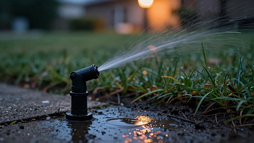
You’ll find the backflow preventer installed immediately downstream of the water meter, mounted vertically in an above‑ground enclosure at least 12 inches above grade. It sits within 18‑36 inches of the meter, before the first zone valve, and provides a 30‑inch clear space for access. The device must be positioned 12 inches above the highest sprinkler and downstream piping, with a double‑check or RPZ assembly per hazard level. Follow the placement checklist for code compliance and testing procedures.
Place the Backflow Preventer Right After the Water Meter
Because the water meter marks the point where municipal supply meets your property, you should install the backflow preventer immediately downstream of it. Position the unit directly adjacent to the discharge side of the meter, within the 100‑foot limit from the right‑of‑way, and keep it inside your property line. Use an above‑ground enclosure at least 12 inches above grade to avoid flood exposure, and guarantee the enclosure has a hinged drain flap sized for the RPZ’s 300 gpm relief rate. Mount the preventer with proper orientation, aligning inlet and outlet ports with flow direction, and employ vertical mounting to maintain gravity‑assist drainage and ease of access for the ball shut‑off valves and test cocks. Follow local code and utility mandates that require the preventer as the first component after the meter. Subterranean vaults are high‑maintenance and increase safety liability. Regular testing of the device ensures it continues to block contaminated water from re‑entering the potable supply. Properly sized backflow preventers protect public health by stopping cross‑connection risks. Installing a preventer near the meter also simplifies compliance with backflow inspection requirements.

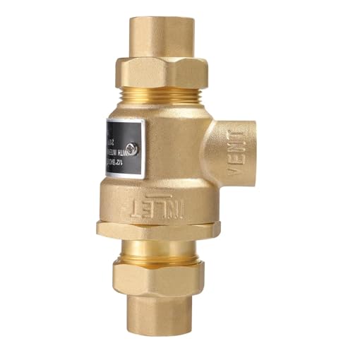
BACKFLOW PREVENTION: The Watts Lead-Free Brass Residential Dual Check Valve Backflow Preventer is ideal for non-health hazard residential water system containment. It is designed to prevent the backflow of polluted water from entering into the potable water supply due to back-siphonage and/or backpressure at the service entrance or at individual outlets.

MEASURE BEFORE PURCHASE -Considering the different thicknesses of different equipment, measure the horizontal circumference and divide it by 2 to obtain the width, and measure the vertical circumference and divide it by 2 to obtain the height. We recommend measuring your backflow system before purchasing to make sure that backflow preventer cover is suitable for your backflow valves system.If you are not sure the size or have any other question about our backflow preventer cover, please feel free to email us, we are pleasure to help you.

Match Assembly Type to Placement Rules
You’ll match each backflow‑preventer assembly to its specific placement rules by first identifying the type—PVB, DCVA, or RPZ—and then applying the code‑mandated height, orientation, and proximity requirements. For PVB assembly positioning, mount the unit vertically with test cocks downward, locate it upstream of control valves, and keep it at least 12 inches above the highest sprinkler head. DCVA placement calls for installation after the shut‑off valve and before zone valves, oriented per manufacturer specs, and positioned where you can access it for annual testing. RPZ assembly positioning requires a ventilated area, a relief valve 12 inches above the highest point, and a 12‑36‑inch elevation above grade for drainage. In every case, treat the backflow preventer as part of the mainline installation, ensuring clearance and accessibility per code. Properly sized solenoid valve can improve system response and reduce pressure fluctuations. Low‑voltage power sources can also be used to operate electric valves efficiently. Sprinkler systems often incorporate built‑in pressure regulators to maintain consistent flow rates across varying elevations.

【UPC & ASSE 1020-2020 Certified Protection】 This 1" pressure vacuum breaker assembly is certified to Uniform Plumbing Code and ASSE 1020-2020 standards, providing code-recognized backflow protection for irrigation, sprinkler, and outdoor water systems.

【Choose Certified Products】ONDAQUA holds the UPC Certification issued by IAPMO, and our products are also compliant with the ASSE 1020-2020 standard

【765 1" & 1-1/4" Repair Kit】All parts work for Febco 765 EBV 1" & 1-1/4" Backflow Preventer and Vacuum Breaker. Maximum working pressure: 150 psi. Perfectly replace for Febco OEM 905-212, 905-052 & 300-089. Replacement part for Febco 765-1 Repair Kit. ( NOT for 1/2" & 3/4" Models)
Backflow Preventer Height Requirements for PVB, DCVA, and ASV
Typically, a backflow preventer must sit a minimum distance above the surrounding surface, and the exact height varies by assembly type. For a PVB, you must locate the device at least 12 inches above finished grade, 12 inches above the highest sprinkler or bubbler, and 12 inches above downstream piping per IRC. The DCVA can be placed above or below ground, but never lower than 12 inches above ground and no deeper than 24 inches, with a maximum elevation of 5 feet above floor or grade. An ASV requires a 6‑inch clearance above the highest emitter or sprinkler, matching AVB standards for low‑hazard systems. Follow backflow preventer manufacturer regulations to avoid common backflow preventer problems such as inadequate clearance, improper support, or inaccessible testing points. Ensure proper backflow protection is installed when the irrigation system draws water from a potable source. Sprinkler valves are designed with water‑resistant seals to prevent moisture intrusion and maintain reliable operation.

Serial number visible in any installed orientation reduces labor time
[Versatile Applications] The backflow preventer is engineered for smaller supply lines, making it perfect for laboratory equipment, processing tanks, sterilizers, and dairy applications. It is particularly recommended for boiler feed lines to ensure that return pressure remains higher than system pressure during operation.Compatible with all major brands.

📏【Perfect Fit for 52"x32" Devices - Measure Guide】 Ensure an optimal fit. Our 3-way opening winter freeze protection cover's outside dimensions are 52"W x 32"H. For best results, measure your device and add 2-3 inches of extra space to both width and height to accommodate the cover's own thickness and ensure easy installation. The Green color blends discreetly into your landscape.
What the Code Says About Meter‑Side Placement
Most codes require the backflow preventer to sit within 18 inches of the water meter and above ground, with a 12‑36 inch clearance for maintenance. You must locate the device on the meter side, ensuring it stays above grade to meet IPC and IRC mandates—six inches above flood‑level rim per IPC, twelve inches above downstream piping per IRC. Jurisdiction specific rules may demand a RPZ when fire‑department connections lie within 1,700 ft of a non‑potable source, or a double‑check assembly for low‑hazard applications. The placement must allow backflow testing requirements to be met without submerging the relief valve. Provide a bypass for meter service and keep drainage paths clear to prevent structural damage while preserving system integrity. Homeowners should verify local permit thresholds before installing a sprinkler system to ensure compliance with building codes. Proper spacing also helps maintain the sprinkler coverage area, reducing the risk of dry spots and ensuring uniform fire suppression. CPVC pipe must be protected from UV exposure and physical damage when installed in exposed locations.
【Dimensions】: Pressure Vacuum Breaker Cover measures 53cmx20cm/20.87inchx7.87inch. Is an excellent winter water meter cover

【Package Included】: You will receive 1x Sprinkler Gate Cover.
【Package Included】: You will receive 1x Sprinkler Gate Cover.
Why Placement Precedes the First Zone Valve
Since the backflow preventer must sit within 18 inches of the meter and above grade, locating it before the first zone valve naturally follows the code‑mandated placement. You’ll see that positioning upstream guarantees proper flow direction toward the valve array, keeping the potable supply isolated from irrigation chemicals. The RPZ or DCV then meets pressure regulation requirements by allowing gradual pressurization; the backflow device absorbs surge pressure before any zone valve opens. This arrangement also provides the mandated 12‑18‑inch clearance for test cocks and maintenance without digging. By installing the device first, you prevent back‑siphonage from reaching the service line, satisfy hazard‑protection standards, and eliminate pressure‑shock failures during start‑up. Reduced pressure zone valves are required when the hazard level is classified as high. The system’s main line distributes water evenly to each zone, ensuring consistent coverage across the landscape. Efficient irrigation can be achieved by aligning sprinkler placement with the water radius specifications of each sprinkler type. Proper pump sizing ensures adequate pressure for the entire system, especially when elevation changes or large distances are involved.
Identify the Correct Spot When Adding a New Irrigation Line
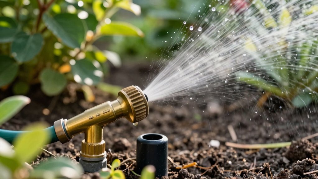
The ideal spot for a new irrigation line is the accessible box immediately downstream of the water meter and upstream of the first zone valve, where the backflow preventer already sits. Position your line in that box, then run the pipe through a proper underground installation to the desired zone. Use a double‑check valve assembly if the line will stay below grade, or a pressure vacuum breaker in an accessible above‑ground location when you need easy maintenance. Keep the pipe at least 12 inches above finished grade for PVBA units, and guarantee the box remains reachable from the sidewalk for future testing. Verify that the new line connects before the first zone valve, preserving protection for the entire system. Annual testing is required to ensure the backflow preventer remains effective. Some systems may employ solenoid valves for automated zone control, but this is not a universal requirement. The valve housing often features a transparent cover that lets you see the internal diaphragm.
How to Test and Certify Your Backflow Preventer?
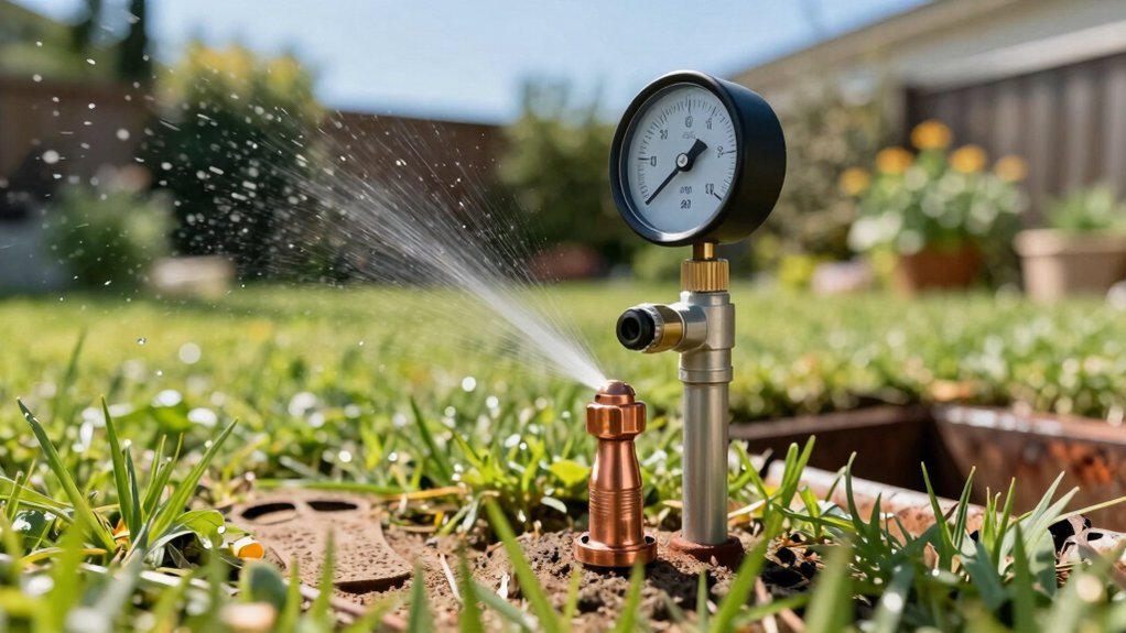
Once the new irrigation line is installed, you must ascertain that the backflow preventer works correctly and obtain certification. Begin by notifying the client, confirming device identification, and inspecting for damage. Attach the test kit hoses to the test cocks, then measure pressure differentials according to the USC 10th Edition standards. Record data, compare against acceptable ranges, and troubleshoot any leaks or pressure anomalies. After a successful field test, tag the device and complete the written and practical examinations required for certification. Remember that annual certification requirements mandate a full retest each year, while ongoing testing protocols require periodic pressure checks and documentation to maintain compliance and guarantee reliable operation. Regular testing also helps verify that the system meets hydrostatic test criteria, ensuring long‑term reliability and safety.

Watts TK-9A Premium Edition with extra line pressure gauge & adapters

Approved by the USC-FCCCHR and CA-NV AWWA

Specially designed for testing backflow prevention assemblies
Verify Clearance and Accessibility for Maintenance
Ensuring proper clearance and accessibility for maintenance means you must keep at least 30 inches of horizontal space between the backflow preventer’s face and any adjacent wall, while also providing a clear path to the test‑cock side for hand‑wheel operation. Measure from the device’s top to the enclosure roof and from its bottom to the concrete slab; both distances must meet code‑mandated clearances. Position access panels so you can reach the gate‑valve hand wheel, meter, and test cock without obstruction. Verify that the side without the test cock can sit closer to the wall, but maintain the 30‑inch rule on the test‑cock side. Account for enclosure heating requirements and enclosure ventilation needs, ensuring adequate airflow and temperature control while preserving the required clearances for safe testing and maintenance. Use waterproof covers to shield the backflow preventer from weather and debris. The wet‑pipe system is the most common type of sprinkler system, offering quick activation and reliability in many climates.
Avoid Common Placement Mistakes & Fixes
Where can you place a backflow preventer without inviting costly errors? Choose a location that stays dry, accessible, and protected from freezing. Avoid flood‑prone spots and outdoor walls that collect snow or ice, because seasonal operation and winterization requirements demand a clear, heated environment. Install the device at a height that allows easy inspection and testing; low benches or underground vaults hinder maintenance and increase debris accumulation. Align the unit exactly as the manufacturer specifies—incorrect orientation disables check valves and can cause worn components to fail early. Size the preventer to match the pipe diameter and flow rate; undersized units restrict pressure, while oversized ones compromise backflow protection. Finally, position it away from construction zones to prevent debris and corrosion from compromising the valve seals. Properly grounding the system reduces electrical hazards and ensures safe operation.
Backflow Preventer Placement Checklist for Compliance
A correctly installed backflow preventer must meet local code, device‑type, height, orientation, and accessibility requirements, so start by confirming the municipality’s approved model and testing schedule before you set the unit. Verify the city‑approved type—pressure vacuum breaker, RP valve, or double check—and guarantee it’s listed for residential irrigation. Position the device at least 12 inches above the highest head or grade, face test cocks upward, and align flow arrows per the manufacturer. Install the assembly inside a double valve box placement to keep debris out and simplify service. Apply proper freeze protection by burying the box below the frost line or adding insulation if exposed. Locate the unit after the stop‑and‑waste valve, before electric zone valves, and confirm free operation with a closure test. Finally, schedule annual testing according to local mandates. Double box installation provides a cleaner and more reliable setup.