Pick an 18‑16 AWG cable, run a white common wire from the controller’s “C” terminal to each valve, and color‑code each zone wire distinctly. Use gel‑filled or silicone‑sealed waterproof connectors, and splice with a brass lug or heat‑shrink for extra strength. Trench 6‑inch wide, 8‑12‑inch deep, laying conduit or direct‑buried cable under the pipe, then backfill compacted soil. Strip, twist, and seal each solenoid lead, then test continuity before powering up; the next steps will show you how to fine‑tune and troubleshoot the system.
Choose the Right Wire Gauge and Color Code for Sprinkler Wiring
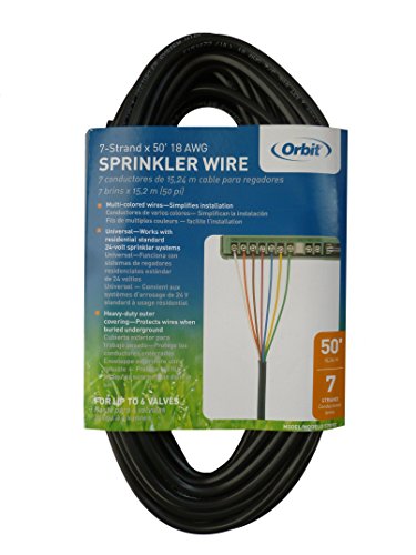
Pick the right wire gauge and color code early, and you’ll avoid costly re‑work later. You select 18‑gauge as the minimum for short runs, but upgrade to 16‑gauge when distance or surge protection demands lower wire resistance management. For runs exceeding 1200 ft, move to 14‑AWG or larger; 12‑AWG caps 1350 ft, and 10‑ or 8‑AWG handles the longest spans. Follow color‑coding rules: white for common, each zone a distinct hue, and keep one extra wire for the neutral. Use multi‑strand conductors for burial flexibility, and route them through cable conduit installation to protect against physical damage and to satisfy code. Align gauge choice with valve manufacturer specs and the 24 VAC, 350 mA inrush, 190 mA holding current tables for reliable operation. A break in the wire will render the system inoperative. Thermostat wire is typically rated for 24 VAC and low current, making it potentially suitable for short‑run irrigation controllers when code compliance is verified. Proper conduit protects wiring from physical damage and ensures fire‑code compliance. Direct bury of sprinkler wire requires UV‑resistant, moisture‑sealed conductors to meet underground installation standards.

【Specification】16 Gauge 5 conductor wire(Black & Red & Yellow & White & Green). Black PVC Jacket. 10ft/3M. Max input voltage: 300V(also can for 5V/12V/24V). Max current: 11A. Rated working temperature from -20℃/-4℉ to 80℃/176℉. Material:PVC+Tinned Copper.Flame retardant:VW-1 and FT1

HIGHLY CONDUCTIVE: NAOEVO electrical wire uses high-precision oxygen-free tinned copper, The outside diameter of the Jacket is 2.7 mm Typ, and 41 strands of 0.14 mm tinned copper wire are inside each circuit, has lower resistance and higher conductivity

Professional Grade: 18-gauge copper conductors with color-coded insulation for easy valve identification
Gather Waterproof Connectors for Sprinkler Wiring
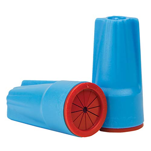
Water‑tight connectors are essential for reliable sprinkler wiring, so you need to gather the right types before you start splicing. Choose gel‑filled connectors for quick twist‑in installations, direct‑bury splice kits for above‑ground or submerged runs, and brass lug connectors with heat‑shrink for mechanical strength. Grease tube connectors and one‑step silicone‑seal units handle 2‑wire paths and high‑humidity zones. Verify each part meets the 600 V rating, copper‑to‑copper compatibility, and #12‑#22 gauge range. Factor in considerations for extreme environments: select components rated –40 °F to 221 °F, UL 486D listed, and corrosion‑protected for DC irrigation lines. If you must work in wet conditions before permanent parts, apply temporary waterproofing methods such as silicone sealant tape or heat‑shrink sleeves, then replace with permanent connectors once the system dries. Low‑voltage control circuits can monitor valve status and integrate with fire alarm systems. Always perform a continuity test after splicing to confirm a secure electrical connection before powering the system. Maintain at least a 12‑inch clearance between any light fixture and a sprinkler head to ensure unobstructed water spray and compliance with fire safety codes.

VERSATILE WIRE RANGE - Accommodates a wide range of wire sizes from #18 AWG to #10 AWG, providing a flexible and dependable solution for various irrigation and low voltage wiring projects with a single connector.

VERSATILE WIRE RANGE - Accommodates a wide variety of wire combinations, ranging from #22-#14 AWG; perfect for diverse electrical projects in Tools & Home Improvement and landscape lighting applications.

Tailored 30PCS Assortment for 12-22 AWG: Stop guessing which connector fits your project. This 30-count of waterproof electrical caps delivers reliable splicing without complex wire charts. It features distinct blue nuts tailored for medium gauges (12-22 AWG). These color-coded housings ensure seamless identification on active job sites, preventing miswiring while maximizing installation speed.
Trench and Protect Wiring: Depth and Placement
After gathering the proper waterproof connectors, you’ll need to trench and protect the wiring. Dig a 6‑inch‑wide trench 8–12 inches deep, adjusting to 12 inches in cold zones or 8 inches in warm climates. Lay the conduit or wire directly beneath the sprinkler pipe, aligning it with the valve‑to‑controller path. Use pipe puller tools to position lines without excess disturbance, then backfill with compacted soil, applying proven soil compaction methods to eliminate air pockets. Install landscape flags or string before digging to mark routes, and employ erosion control strategies on slopes to prevent washout. Verify depth at multiple points, guarantee the trench meets the pipe‑diameter‑plus‑4‑inch rule, and keep the installation tight and uniform for reliable performance. You can also use a metal detector to help locate existing underground lines before you start digging. Remember to follow the step‑by‑step guide for using a metal detector to accurately locate sprinkler heads. Call 811 before any digging to ensure all underground utilities are marked and avoid accidental damage.
Find and Prep the White Common Wire for Every Valve
When you locate the controller’s “C” terminal, you’ll see a single white wire—often labeled “C” or “Com”—that serves as the common for every valve. Identify that wire in the bundle, confirm it’s the extra conductor, and trace it back to each valve. Use proper cable management techniques: strip the white wire only as needed, keep the stripped length under ¼ inch, and twist a clean segment from each solenoid together. Planning wire routing paths, pull the bundle loosely, leaving a few extra feet at each valve for future repairs. Secure the twisted bundle with a waterproof wire nut, then route the assembly through PVC conduit or zip‑tie bundles, burying it 6–12 inches deep with 16‑gauge direct‑burial cable. Label the ends “Common” for reference. Each valve also has a colored wire that connects to its specific zone control. The solenoid creates a magnetic field that opens the valve when energized. Standard solenoids often share the same voltage and pressure specifications across many brands. The system typically operates on low‑voltage AC to improve safety and energy efficiency.
Professional Grade: 18-gauge copper conductors with color-coded insulation for easy valve identification

【Specification】 100FT 16/2 Conductors, SPT-2 black PVC insulation, pure copper, VW-1 fire resistant, maximum working volt 300V. Great for low voltage use.

Professional Grade: 18-gauge copper conductors with color-coded insulation for easy valve identification
Connect Sprinkler Valve Solenoids and Seal With Silicone Caps
Connect each zone wire to its corresponding solenoid lead, then twist the remaining lead from every valve together with the common white wire. Strip 10 mm of sheathing at the controller and 20 mm at each valve, exposing clean copper. Twist the common bundle firmly, then secure it with a waterproof wire connector filled with silicone gel. Apply a silicone cap over each connector, pressing until the seal is uniform and airtight. Verify that each cap covers the joint completely, ensuring proper silicone sealing that protects wire connections from moisture and corrosion. Use heat‑shrink tubing where extra strain relief is needed, but keep the overall profile compact. This method yields a reliable, sealed network ready for controller attachment. Proper pressure regulation is essential for consistent flow, especially when using in‑line pressure regulators in high‑pressure zones. Adding a pressure regulator near the water source helps maintain steady flow throughout the system. Remember that most sprinkler solenoids are polarity‑agnostic and will operate correctly regardless of lead orientation.
For connections exposed to condensation, water, vapors or dust

Versatile Compatibility: Fits AWG #22-#12 wires, making it a medium size connector suitable for a range of applications.
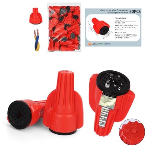
✅Industrial-Grade IP68 Waterproof & All-Weather Protection: Our waterproof wire connectors feature a triple-seal design with pre-filled industrial-grade silicone gel and a rugged thermoplastic housing, achieving an IP68 waterproof rating. They withstand dust, corrosion, and extreme humidity, making them the ultimate waterproof electrical connectors for wet, buried, or exposed installations in irrigation systems, landscape lighting, and outdoor machinery. Note: This product is not fully submersible in water. It features surface water resistance and is suitable for use in damp environments.
Route Sprinkler Zone Wires From Controller to Valves
A well‑planned route starts at the controller and runs each zone’s hot wire and the common wire directly to its valve, keeping the bundle tight against pipe runs and away from foot traffic. First, identify wiring entry points on the controller and at each valve box. Pull a dedicated 6‑strand cable—one white common, five colored hots—through the entry slot, then tuck the bundle under existing pipe chases. Keep the wire organization strict: separate each zone’s hot strand from the common, and avoid mixing colors. From the controller, run the bundle straight to the furthest valve, then backtrack to nearer valves, leaving a few inches of slack at each connection. Guarantee the path skirts walkways, driveways, and concrete barriers, using sleeves where needed, and keep the bundle snug against the structure. Use 16 gauge direct burial irrigation wire for added durability and protection. Properly sizing the system for water pressure ensures consistent coverage across all zones. Even distribution helps prevent over‑watering and promotes healthy plant growth. Understanding the flow rate limits for each zone is essential for maintaining optimal spray patterns.
Fasten Wire Bundle With Staples and Tape
Because you’ll already have the wire bundle in place, secure it with insulated staples and tape to keep the run tidy and protected. Position each insulated staple around the bundle without piercing the insulation, then hammer lightly so the legs clasp the wire on both sides. Align the staple edge with the stud edge for precise placement, using a finger to feel the catch before full drive. Space staples uniformly with a measuring stick, allowing a loose hold that lets the wire expand and contract. Add a strip of electrical tape over each staple to reinforce the connection and prevent movement. This method organizes wire bundles, supports wire against wall, and maintains a clean, compliant installation. Tabs on the staple prevent over‑hammering while holding the wire securely. You can also use a magnetic tracer to locate the sprinkler solenoid quickly if the wiring is hidden. A faulty solenoid often shows irregular watering patterns, indicating a need to check voltage before replacement.
Test Sprinkler Wiring Continuity and Valve Action
With the bundle secured, you now verify that each wire carries a signal and that the valves respond correctly. Use the multimeter in continuity mode, connecting the black lead to the common wire and the red lead to each zone wire. Listen for the beep; a tone confirms a path, but remember it doesn’t guarantee quality. Power off the controller before testing to avoid false readings. Switch to voltage mode and measure between zone and common terminals; expect 22‑28 V. Anything lower signals a controller issue. Next, isolate each solenoid, set the meter to ohms, and check resistance; 20‑60 Ω indicates a healthy valve. Values outside that range point to shorts or opens, guiding further sprinkler diagnostics. A functioning transformer will read 24‑28 VAC at its screw terminals.
Troubleshoot Sprinkler Wiring Issues and Re‑seal Connections
You’ll start by turning off power and water, then inspect the controller for error codes and loose terminals; any faulty zone will point you to the problematic wiring. Next, troubleshoot controller connections by tightening each terminal, cleaning corrosion, and confirming voltage with a tester. Locate each valve box, open it, and visually scan for frayed or cut wires. Use a multimeter in continuity mode to differentiate cut dedicated wires from common cuts. When you find a damaged section, cut it out, strip the ends, and repair underground splices with waterproof connectors or direct‑bury splice kits. Secure each splice, re‑seal with water‑safe wire nuts, and verify that the repaired zone operates correctly before restoring power and water. Ensure the common wire is properly connected to avoid intermittent zone failures.

PetsTEK Wire Splice Kit for Electric In-Ground Dog Fence Systems. Compatible with All PetSafe, SportDog and Dogtra Underground Fence Systems.

🎖️ 10 Waterproof Wire Connectors (Splices) for installation or repair of any wired electric dog fence system (Invisible Fence, SportDog, Perimeter Technologies, and ALL others)

Package Includes:This underground wire splice kit includes 2 rated butt splices and 2 heat shrink tubes. The kit is designed to work with a range of voltage conditions and supports a maximum voltage rating of up to 600 volts. These components are intended for use with direct burial UF cables and can be applied to various underground and outdoor wiring connection and repair projects