You’re probably facing a blockage, wrong temperature, or heat‑creep. Check pressure spikes and motor current to spot a clog, then run a pin test or cold‑pull with nylon filament. Make sure the nozzle’s at 180‑220 °C for PLA, 220‑250 °C for PETG, or 210‑250 °C for ABS, and keep the bed properly heated. Verify the first‑layer gap is ~0.2 mm and the bed is level, and boost the cooling fan while adjusting retraction to stop heat‑creep. If you keep going, you’ll uncover deeper troubleshooting steps.
Identify the Exact Cause of a Nozzle Clog in Seconds
You can pinpoint a nozzle clog in seconds by watching the filament’s behavior as soon as the hotend heats up. When the first layer fails to extrude or the nozzle drags filament, note the pressure spikes: a sudden stall indicates a blockage, while a gradual slowdown points to partial obstruction. Identify nozzle pressure fluctuations by monitoring the extruder motor current; a sharp rise signals a mesh‑like build‑up from dust or carbon‑fiber particles. Examine previous print history for recurring issues—if earlier jobs with the same filament showed under‑extrusion, moisture absorption or diameter inconsistencies are likely culprits. Cross‑reference the filament’s storage conditions and quality grade; low‑quality or poorly stored material often introduces debris that clogs the tip within minutes of heating. Dust particles from the environment can quickly accumulate at the nozzle tip, causing immediate blockages. A simple pin test can verify if the nozzle tip is obstructed by gently probing the opening after heating. Checking the spray pattern after a short test run can reveal uneven flow indicative of a clog. Warm water can also be used to soak the nozzle tip, loosening dried filament residue before scraping.

Precision Cleaning Needles:20 specialized 3D printer nozzle cleaning needles, 0.4mm in diameter, easily penetrate nozzles to clear stubborn clogs. As a 3D printer nozzle cleaner, they are designed not to damage sensitive components, delivering a thorough and safe clean

【Packaging Includes】1x nozzle cleaning needle with handle, 10 stainless steel nozzle cleaning needles with a storage box, and 1x copper wire cleaning brush. This kit is designed to help you easily solve all nozzle and extruder blockage issues.

Complete Cleaning Kit: This nozzle cleaning kit includes a 1.5mm clog poke, 20x 0.4mm needles, and a wire brush. Handles filament jams and burnt residue efficiently
Clear the Nozzle With Wire or Cleaning Filament
Once you’ve identified the blockage by monitoring pressure spikes, grab a fine‑gauge stainless‑steel needle (≈0.3 mm) and insert it into the heated nozzle. Gently push the needle up, down, and back‑and‑forth; the 0.3 mm diameter fits 0.4 mm or larger nozzles and clears most obstructions without damaging the bore. If the needle alone doesn’t free the flow, heat the nozzle to 200 °C for PLA (or higher for PETG/ABS) and perform a cold‑pull with nylon or dedicated cleaning filament. Cool to 90‑110 °C, then pull the solid filament out to extract residual debris. For stubborn clogs, consider ultrasonic nozzle cleaning or, if needed, disassemble print head and soak the removable nozzle in solvent before re‑installing. Dust buildup in the workshop can also contribute to frequent clogs. Proper ventilation is essential when using solvents to avoid inhalation hazards. The nozzle’s design leverages Bernoulli’s principle to convert pressure into increased fluid velocity. A well‑maintained system can also improve overall water efficiency, aligning with the goals of the Nozzle X upgrade.
Pick the Right Temperature for PLA, PETG, or ABS to Prevent Nozzle Clogs
If you set the nozzle temperature within each filament’s ideal range—180‑220 °C for PLA, 220‑250 °C (up to 255 °C) for PETG, and 210‑250 °C (often 230‑255 °C) for ABS—you’ll keep the plastic fully molten, avoid premature solidification, and dramatically reduce the chance of clogs. For PLA, start at 200 °C and adjust in 5 °C steps; keep the bed at 20‑60 °C and use 100 % cooling to prevent melt buildup. With PETG, a 245 °C baseline works for most brands; fine‑tune by ±5 °C while maintaining a 65‑90 °C bed to avoid brittle layers. ABS demands 230‑255 °C nozzle and a 90‑110 °C bed; manage enclosure temperatures around 40‑50 °C to curb warping without exceeding material limits. Incremental temperature tweaks and proper enclosure control keep nozzle flow smooth.

Temperature Activated Tri-Color Shift: This thermochromic PLA filament features a sensitive temperature color-changing effect. It appears Pine Green at temperatures below 31C, gradually turns Light Orange when the temperature exceeds 31C, and fully changes to bright yellow above 45C, bringing vivid and magical visual changes to your printed models. Note: Avoid prolonged direct sunlight exposure, as long-time UV radiation will accelerate color fading and weaken the temperature-sensitive discoloration effect
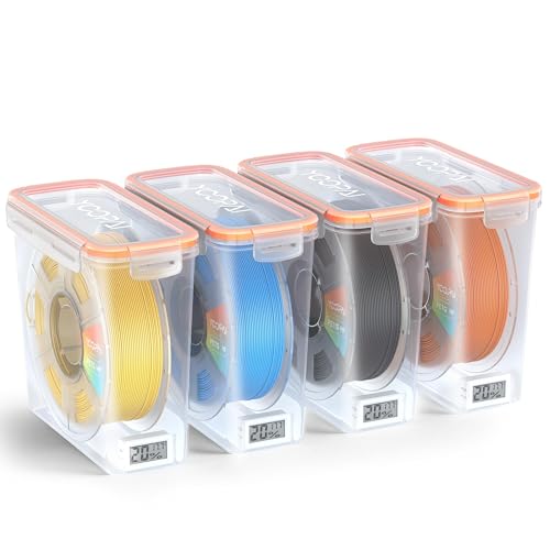
Visible Temperature And Humidity Monitoring For Smarter Filament Storage:This Pro filament storage box features 4 packs built-in temperature and humidity monitor, so you can check storage conditions at a glance instead of guessing when filament is ready to use. For makers who want more visibility into daily filament storage, it adds a more informed and controlled way to manage 3D printer filament storage

Color Changing PLA Filament,Color Changing with Temperature.
Correct First‑Layer Height and Bed‑Leveling to Avoid False Clogs
When the nozzle sits too close to the bed, the filament gets squished, creating excess pressure that blocks flow and mimics a true clog; a 0.2 mm gap—checked with a sheet of paper or a feeler gauge—provides the ideal “squish” for most 0.2 mm layer heights, while a negative Z‑offset of about –0.05 mm yields roughly 25 % filament compression. Measure the gap at four points; adjust the bed until the paper slides with a faint tug. If the first layer surface quality shows smudges or gaps, raise the Z‑offset in 0.01 mm increments. After leveling, print a test skirt, then fine‑tune print speed adjustment to keep extrusion consistent. A uniform first layer eliminates false clogs and stabilizes subsequent layers. Proper sprinkler head height ensures even water distribution, analogous to maintaining the correct nozzle‑to‑bed distance for consistent extrusion. Adjusting the nozzle depth also mirrors how soil type influences the optimal depth of sprinkler heads for efficient watering. Selecting the appropriate ceiling height for a pop‑up sprinkler maximizes coverage and compliance with fire safety standards.
Eliminate Heat‑Creep by Tuning Cooling Fan Speed and Retraction
Although the nozzle can stay cool, excessive heat traveling up the hotend—known as heat‑creep—softens filament before it reaches the tip, causing jams. First, verify the extruder cooling fan runs at its rated voltage (12 V or 24 V). A multimeter reading below spec means lower RPM and higher creep risk; replace wiring or the fan if it spins intermittently. Next, set fan speed to 100 % in your slicer, then lower in 10 % steps until the problem disappears. Install a cooling shroud to channel airflow directly onto the heat sink, and employ a fan spacer to redirect air upward, keeping the hotend cooler. Combine these hardware tweaks with a modest retraction increase (e.g., 0.5 mm) to pull filament away from the heat break, preventing softening before it reaches the nozzle. A fan spacer can be printed at home for a low cost, making it an accessible heat‑creep killer for many printer models. Understanding local fire codes helps ensure your printer setup complies with safety regulations. Properly sizing the low‑voltage power supply can also improve energy efficiency and reduce heat‑crep risk.

Materials: Plastic
Perfect Compatibility for Bambu Lab H2D – Designed specifically for Bambu Lab H2D printers. This hotend cooling fan matches the original mounting structure for a precise fit, secure installation, and reliable replacement performance.

Compatible 3D Printers: The 2 packs cooling fans are compatible with Ender 3 V3 SE/Ender 3 V3 KE/CR10 SE 3d printers, included 24V 4010 turbo fan and 24V 2510 fan, please confirm your 3d printer model before ordering.
Replace a Damaged Bowden PTFE Tube to Stop Leaks and Blockages
Heat‑creep isn’t the only cause of jams; a worn Bowden PTFE fitting can let filament slip, leak, and block the hotend. First, detect worn bowden tube fittings by feeling the lock collar’s spring tension—if it feels loose, the teeth have deteriorated. Look for filament seepage or the tube slipping during retraction. When you confirm wear, replace aging ptfe tubing: push the tube into the fitting while holding the collar, release tension, then pull the tube out with steady pressure. Trim the end with a PTFE cutter to a clean, square edge. Install a new fitting, screw it securely, and fully seat the fresh tube. Verify the collar springs correctly and run a test extrusion to guarantee no leaks or blockages. Regular inspection of Bowden tube fittings can prevent unexpected extrusion failures. O‑ring wear can also contribute to leaks and should be checked during maintenance. Flex Tape’s waterproof seal is designed for rigid surfaces, making it unsuitable for high‑pressure hose repairs. Understanding solenoid compatibility helps ensure the correct valve operation in irrigation systems.

【Original Quality】: 100% original Creality official K1 series PTFE tube kit 2M; Selected the high-quality PTFE material. Good quality, low loss rate; It is especially compatible with K1, K1C, K1 SE, K1 Max, Ender-3 V3, Ender 3 V3 Plus, K2 Plus, Creality CFS filament system, K2 Plus, K2 Pro, K2, and Other 3D FDM Printers

[Broad 3D Printer Compatibility]: Designed for 1.75mm filament systems, this tubing (2.5mm ID×4mm OD) works with direct-drive extruders in popular printer designs, including models requiring standard PTFE tubing dimensions

Smooth and Reliable Filament Flow: Made from high-quality PTFE material, this Bowden tube for 1.75mm filament ensures smooth and consistent filament feeding, reducing the risk of clogs and enhancing your 3D printing results. Experience a hassle-free printing process with minimal interruptions, allowing you to print with confidence every time.