First convert each sprinkler’s GPM to CFM using the 7.48052 factor, then multiply the resulting CFM by 1.5‑2 to cover friction. Keep the system pressure within pipe limits—40‑80 psi for rigid PVC and ≤50 psi for polyethylene. For residential zones aim for 2‑3 CFM, scaling up to 20‑40 CFM for commercial flows (e.g., 150 GPM ≈ 20 CFM). Choose a compressor with at least a 30 % safety margin and match it to a tank sized 4‑10 gal per CFM for continuous flow. If you follow these steps, you’ll uncover the exact sizing details you need.
Calculate CFM From Sprinkler GPM for Compressor Sizing
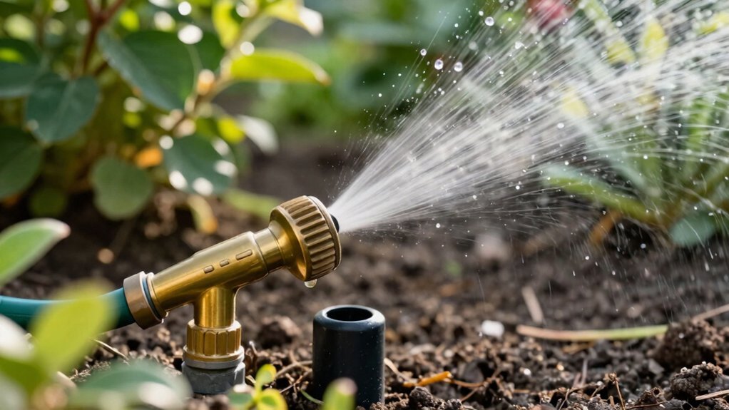
A quick way to size your compressor is to translate the sprinkler’s flow rate—measured in gallons per minute (GPM)—into cubic feet per minute (CFM) using the 7.48052 conversion factor. First, determine each sprinkler head GPM with a bucket test: fill a 5‑gallon bucket, record the seconds, then compute GPM = (5 ÷ seconds) × 60. Sum the GPM of all heads in the zone; for example, six heads at 2 GPM each total 12 GPM. Convert the total GPM to CFM by dividing by 7.48052, yielding roughly 1.6 CFM. For blowout compressor selection, multiply this base CFM by 1.5–2 to accommodate friction and guarantee efficient clearing. This systematic conversion ensures the compressor meets the zone’s airflow demand without over‑specifying. The bucket test provides an accurate measurement of available water flow. Properly accounting for sprinkler coverage area helps prevent undersized compressors that could leave sections of the system under‑pressurized. The flexible tubing of a hose allows it to adapt to varying pressures while maintaining flow continuity. Hydraulic head loss must also be considered when selecting a compressor to ensure adequate pressure throughout the system.
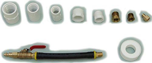
Adapter to winterize underground irrigation sprinkler systems.

Function: The adaptor suitable for winter use in underground irrigation sprinkler systems.

Package Includes 2 x Metal Air Compressor Silencers and 6 x Air Compressor Filter Replacements. Thread Size is 1/2"PT 20mm, Overall Size (Diameter x Height) is 4" x 2.8". (PLEASE check and confirm the detailed size information before purchasing!!)
Pick PSI for Pipe Material & System Size (Sprinkler Compressor)
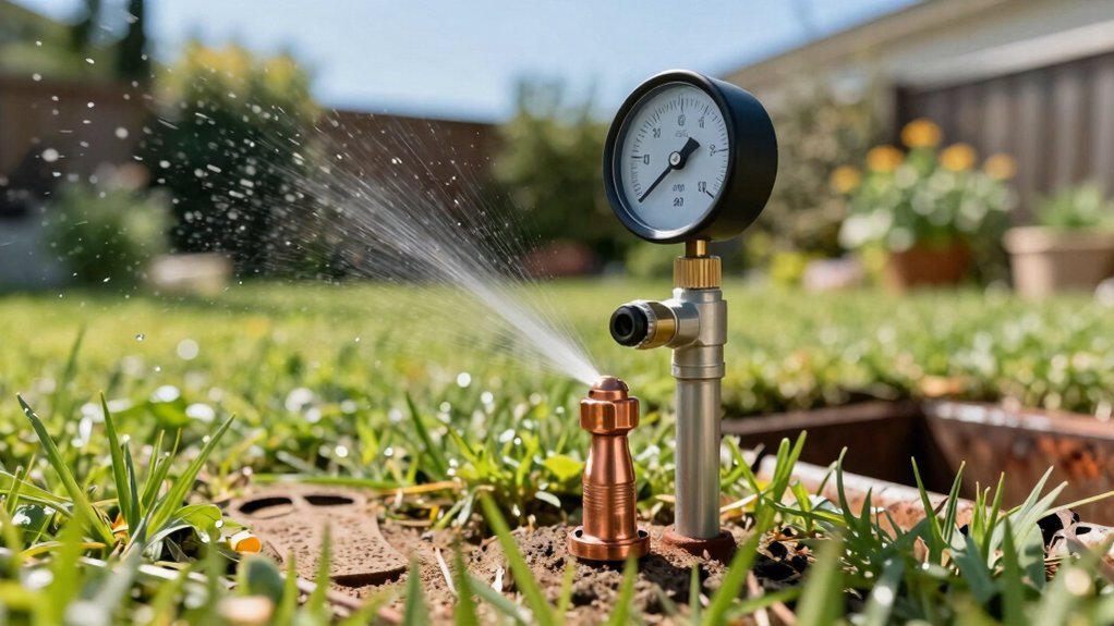
Choosing the right PSI hinges on pipe material and system size, so you’ll match pressure to the limits of PVC or polyethylene while ensuring the blower can reach every head. For rigid PVC, keep PSI between 40 and 80, never exceeding the 80‑PSI ceiling that protects pipe integrity. Polyethylene caps at 50 PSI, so set the system at or below that value, using short bursts to avoid prolonged stress. Align pump capacity requirements with these limits: a pump delivering 50‑80 PSI satisfies most residential zones, while a 40‑PSI minimum covers three‑head, 9 GPM zones briefly. Remember sprinkler pressure limitations dictate minimum viable pressure for head pop‑up and distance compensation, so adjust PSI upward only when longer runs demand it, never surpassing 80 PSI. Rotary screw compressors provide constant high CFM for efficient blowouts, making them ideal for larger residential systems. Ensure compliance with local plumbing codes, as many jurisdictions require approved irrigation‑grade PVC for sprinkler blowouts. The watering cycle timing is also critical for preventing over‑pressurization during blowouts.
Minimum Compressor CFM for Residential & Commercial Sprinkler Systems
Two to three CFM per zone is the baseline for most residential sprinkler systems, but you’ll need to scale that figure up when you move to larger commercial installations. For a residential zone delivering 10 GPM, divide by 7.5 to get roughly 1.3 CFM; most experts recommend 4‑5 CFM at 80‑100 PSI to overcome pipe friction. Commercial zones follow the same rule: a 150 GPM area needs 20 CFM, a 225 GPM area 30 CFM, and a 300 GPM area 40 CFM. Multiply by the number of zones to set total capacity. Keep system maintenance schedules in mind—higher CFM units wear faster, so plan compressor run time limitations accordingly. Choose rotary‑screw compressors for steady output, and avoid pancake models; 15‑plus‑gallon setups provide the reliability needed for both residential and commercial blow‑outs. Reciprocating compressors can also meet short‑term demand when paired with adequate tank capacity. Pancake compressors typically lack the sustained airflow needed for large‑scale sprinkler blow‑outs. Proper nozzle design ensures the pressure is maintained across the system. Understanding fog nozzle atomization helps optimize water distribution during blow‑outs.
What Tank Size Do You Need for Continuous Sprinkler Compressor Flow?
Sizing your air‑tank correctly is pivotal for maintaining steady pressure during a continuous sprinkler blow‑out, because the tank acts as a buffer that smooths out compressor pulsations and prevents pressure drops between zone cycles. To match a 25 CFM compressor, aim for 100–250 gallons; for 50 CFM, target 200–500 gallons. Use the 4–10 gallons‑per‑CFM rule when factoring operational settings and seasonal considerations, such as winter freeze‑risk or summer peak demand. Larger tanks (30 + gallons) eliminate pressure loss during long zone runs, while 60 + gallons become essential for 15 CFM+ units. If you run multiple shifts or have uneven demand, increase storage to avoid over‑working the compressor. Apply the fill‑time formula to verify that your tank meets NFPA’s 60‑minute limit for dry systems. Pump pressure must also be adequate to overcome elevation changes and local water‑supply constraints. Understanding how municipal water integrates with your irrigation system helps ensure compatible pressure and flow rates. A pressure tank can also reduce pump cycling and protect against water hammer.

[Portable and Convenient]: This lightweight 5-gallon air tank features a compact design with a built-in handle, making it easy to carry and transport compressed air wherever you need it, whether at home or on the go

2-way direct-acting valve. Air compressor tank drain valve. Time interval ( OFF ): 0.5--50 minutes (adjustable). Discharge time ( ON ): 0.5--10 seconds (adjustable).

High Quality - Made of high quality braided steel with brass head, this kit is durable, rust and corrosive resistant.
Avoid Common Sprinkler Compressor‑Sizing Mistakes
A common pitfall is selecting a compressor that’s too small, which lets pressure drop more than 10 % and forces the pump to run longer, raising energy use by 5‑7 % per 10 psi loss. You must first calculate peak CFM demand, then add a 30 % safety factor to cover simultaneous tool use and unexpected spikes. Next, evaluate compressor location considerations: keep the unit near the sprinkler network to minimize pipe length, avoid excessive bends, and choose a placement that limits horizontal oversized sections where moisture can settle. After sizing the compressor, match it to air storage needs by selecting a tank that can buffer the required 30‑minute fill at 40 psi, ensuring the system maintains steady flow without over‑purging. Finally, verify that pipe diameter, fittings, and elbows are accounted for, using a 1.7 multiplier for bends, to keep total pressure drop within the 10 psi limit. Proper backflow protection is essential to prevent contaminated water from re‑entering the potable supply during irrigation. Installing a backflow preventer on a garden hose can safeguard your home’s water supply from cross‑contamination. A well‑designed system also incorporates a reduced pressure zone to further protect against backflow incidents.
Blow‑Out Checklist: One Zone at a Time
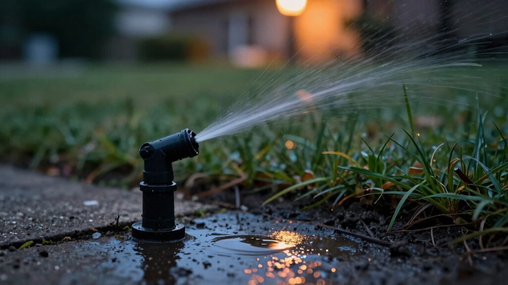
After you’ve sized the compressor and matched it to the required air storage, move on to the blow‑out checklist, tackling one zone at a time. Begin with the farthest, highest‑elevation zone, close its backflow isolation valve, then open the compressor hose attachment. Gradually open the valve, keeping pressure under 50 psi for polyethylene or 80 psi for PVC, and monitor it throughout the air introduction duration. Observe the spray shift from stream to mist; when water disappears, run the zone for roughly two minutes—this defines the system blow out duration. Close the valve immediately, then advance to the next zone, repeating the same steps. Avoid re‑blowing completed zones to prevent friction and heat damage. Continue until the zone nearest the compressor is fully purged. Be aware that water can freeze in the pipes when temperatures drop below 32°F and cause damage. Properly draining the system before the first freeze can also help prevent pipe burst incidents. Regular winterization protects the system from frozen water damage and ensures reliable operation when spring returns.