The steering nozzle sits on the hull’s rear, directly behind the jet pump’s impeller, and pivots with the handlebars via a cable‑linked steering column. It’s a rear‑projecting, aft‑facing device that aligns with the impeller exit and works with the prop shaft’s continuous spin. You’ll find it just aft of the intake grate, with a transparent cover exposing its internal diaphragm. Its precise placement and cable tension are vital, and the next sections will show you how to access, adjust, and maintain it.
Identify the Rear‑Mounted Steering Nozzle on Your PWC’s Hull
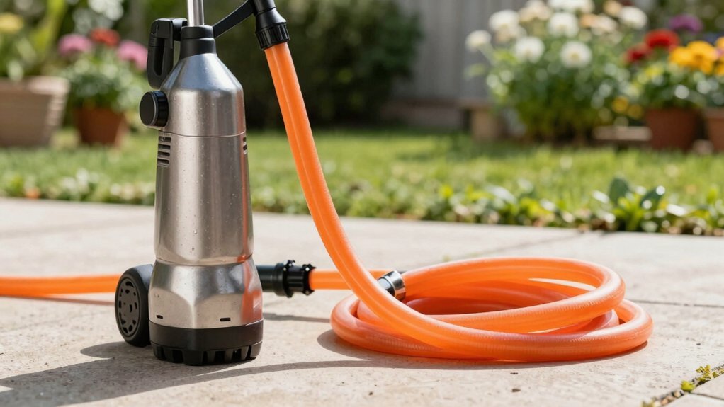
Because the steering nozzle is mounted at the stern, you’ll find it just behind the jet pump and impeller on the rear hull. You’ll recognize it as the small, rearward‑projecting device that pivots left or right when you turn the handlebars. Follow the nozzle positioning guidelines: locate the component after the drive shaft path, distinct from the intake grate and impeller, and confirm its label on PWC diagrams. Guarantee proper nozzle alignment by checking that the high‑velocity water expulsion point faces straight aft when the handlebars are centered. The nozzle’s linkage to the handlebars provides thrust‑based directional control; without active water expulsion, steering ceases. Verify clearance, then adjust or service only with the required 12 mm and 14 mm bolts removed. Remove the bottom nut before accessing the steering rod end. Selecting a hose with an adequate pressure rating ensures safe operation and prevents hose failure. When using a power washer, ensure the hose’s maximum pressure rating exceeds the washer’s output to avoid burst hazards. Standard hose thread sizes such as ¾‑inch and ½‑inch are common for connecting the hose to the PWC’s water inlet.
How the Nozzle Links to the Jet Pump and Prop Shaft
When you turn the handlebars, the steering column pulls cables that pivot the nozzle, while the prop shaft continuously spins the impeller inside the jet pump to generate the high‑pressure water stream. The nozzle sits directly behind the pump housing configuration, aligned with the impeller’s exit port. Prop shaft integration design positions the shaft within the housing so its rotational energy drives the impeller without interruption. Water flows from the intake, through the stator, and exits the impeller at high velocity, entering the nozzle’s throat. Cables link the steering column to the nozzle pivot arm, allowing left‑right deflection while the shaft maintains constant RPM. This arrangement guarantees the jet’s thrust remains steady and the steering response stays precise. The nozzle accelerates the water, converting static pressure into dynamic pressure, as described by Bernoulli’s principle. This transformation follows the continuity equation, which dictates that the product of cross‑sectional area and velocity remains constant. Proper nozzle selection also improves spray uniformity, reducing waste and enhancing performance.
How to Access the Steering Nozzle on Yamaha, Sea‑Doo, and Kawasaki
The steering nozzle sits directly behind the jet pump’s impeller, and accessing it on Yamaha, Sea‑Doo, and Kawasaki models follows a similar sequence: first secure the craft on a trailer or lift, then slacken the handlebars to relieve cable tension. On Yamaha, remove the bottom nut on the steering connection with an Allen wrench, pop the reverse‑gate rods, then use a 12 mm socket on the top bolt and four 14 mm bolts below to begin the nozzle removal procedure. Lift the reverse gate to expose the top pump bolt, and pull the steering kit off after all 14 mm bolts are extracted. For Sea‑Doo, open the rear hull panels, detach cable linkages, unbolt the rear mounting hardware, and lift the intake grate if needed. Kawasaki requires removing the transom reverse gate, unscrewing 14 mm bolts, disconnecting internal steering cables, and extracting the nozzle rearward after clearing the pump water flow path. Follow these nozzle disassembly steps precisely, and keep the engine off throughout. The compact housing often features a transparent cover that reveals the internal diaphragm. Selecting the proper nozzle size is essential for achieving the desired spray pattern and maintaining optimal flow rate.

Adjustable Dual Spray Pattern: This windshield washer nozzles kit features nozzles with an adjustable angle. You can easily fine-tune the water spray direction to ensure optimal coverage and cleaning efficiency across your entire windshield for a clear view.

Durable Material: This windshield washer hose kit is crafted from rubber, featuring flexible and resilient properties that resist cracking and aging. The hose connectors are made of impact-resistant plastic that won't break easily. This ensures your wiper kit remains durable and long-lasting.

Package Includes: This complete kit includes one 13-foot/4-meter high-quality rubber hose and 30 windshield washer fluid hose connectors (10 T-type, 10 Y-type, and 10 I-type) to meet various connection needs.
Adjusting and Realigning the Rear Nozzle for Optimal Steering
Precision matters when you adjust the rear nozzle, because even a slight misalignment can diminish thrust direction and steering response. First, lift the reverse gate, remove the 12 mm top bolt and four 14 mm lower bolts, and separate the steering connection sleeve. Turn the handlebars and verify the nozzle follows left‑right movement; any lag indicates locked steering mechanism adjustments are required. Check cable tension and guarantee the stator aligns with the nozzle’s flow path. Apply the nozzle tolerance recommendations: maintain a ±0.2 mm clearance between the nozzle tip and the stator housing. Re‑install bolts to the specified torque, then test under throttle to confirm the thrust vector matches handlebar input. This realignment restores precise steering authority. Nozzle function is to shape and direct fluid flow, distinguishing it from a valve that merely controls passage. Understanding spray patterns helps optimize nozzle selection for both irrigation and cleaning tasks. A well‑designed nozzle promotes steady uniform flow by minimizing turbulence and keeping pressure consistent throughout the system.
Safety Checklist and Maintenance Tips for Your Rear Nozzle
After realigning the rear nozzle, you should run a safety checklist before hitting the water. First, perform nozzle inspection procedures: verify the nozzle pivots left and right without binding, confirm the intake grate is clear, and guarantee the reverse gate lifts freely. Next, conduct nozzle tightness verification by torquing the 12 mm top and 14 mm bottom bolts to spec, checking the steering rod connection for play, and confirming the drive shaft links are wear‑free. Inspect the jet pump and impeller for damage, and test high‑pressure water expulsion during throttle application. Lubricate rod ends and cable connections, flush the cooling system, and schedule an annual professional jet‑drive disassembly. Optimizing irrigation coverage can also reduce water waste and improve overall system efficiency. Follow these steps to maintain precise steering control and prevent water‑flow obstruction. Regularly inspect the wiring for moisture damage to avoid corrosion and electrical hazards. Adding a water‑proof cover to the valve area protects it from debris and weather exposure.