You’ll find that a nozzle doesn’t generate pressure; it simply takes the pressure the pump already supplies and transforms it into speed. As the flow passes through a narrowing passage, the static pressure drops while the kinetic energy rises, following Bernoulli’s principle and the continuity equation. A smaller orifice makes the fluid faster, but the pressure at the throat is lower, not higher. If you keep going, you’ll see when a nozzle can actually boost pressure and when it can’t.
Does a Nozzle Raise Pressure? – The Short Answer
If you think a nozzle creates pressure out of thin air, you’re mistaken; the pump supplies the pressure, and the nozzle merely converts flow into that pressure. You must recognize that nozzle orientation determines how the restricted flow translates into a pressure rise; a misaligned nozzle can cause uneven pressure distribution and reduced efficiency. The pump delivers a fixed flow rate, and the nozzle’s orifice size inversely sets the pressure: a smaller opening yields higher psi, while a larger one drops it. However, nozzle fouling—deposits that narrow the passage—effectively reduces the opening, unintentionally elevating pressure and risking pump overload. Selecting the proper nozzle size for the pump’s flow capacity guarantees stable pressure, prevents fouling‑induced spikes, and maintains reliable performance. The impact force is directly related to nozzle pressure, not the nozzle type. Understanding momentum change helps predict the thrust generated by the nozzle. This transformation follows the principle of energy conversion as described by Bernoulli’s equation.
❤【Premium Quality】Made of tough brass and stainless steel,resistant to corrosion and fading.

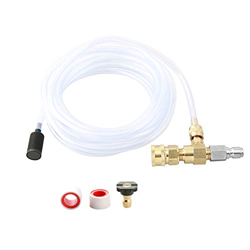
【PRESSURE WASHER TURBO NOZZLE USE】This 1/4 inch quick connect rotating turbo nozzle for pressure washer replacement features an adjustable spray tip configuration. It serves as a direct setup tool to optimize water output lines cleanly

Widely Used --- This fountain nozzle is beautiful in shape, easy to install, and can be used in many ways to amazing results. The fountain nozzle is suitable for courtyards, garden basins, park fountains, hotel fountains.
Bernoulli’s Principle: How Nozzle Pressure Turns Into Speed
A nozzle converts the fluid’s pressure energy into kinetic energy, so the fluid speeds up as it passes through the converging section. By Bernoulli’s principle, the total pressure \(P_{ext{total}} = P + rac12\rho v^2\) stays constant along a streamline for steady, incompressible, horizontal flow. As the cross‑section shrinks, velocity \(v\) rises, forcing static pressure \(P\) to fall. In converging‑diverging designs, the first contraction follows this rule, while the subsequent expansion can generate internal shockwaves that abruptly raise pressure and reduce speed. You can predict the pressure drop with \(P_1 + rac12\rho v_1^2 = P_2 + rac12\rho v_2^2\). The relationship explains why a hose nozzle can accelerate water from a few meters per second to tens of meters per second while the outlet pressure approaches atmospheric. Bernoulli’s principle also explains why a ping‑pong ball can hover in a fast moving stream from a hair dryer, as the high‑speed air creates a region of low pressure above the ball. In a diverging section beyond the throat, the flow continues to accelerate because the decreasing pressure and density allow the expanding area to convert thermal energy into kinetic energy, a process described by the compressible flow equations. Proper nozzle sizing can also protect downstream components by limiting excessive pressure, a benefit highlighted in industrial fluid control practices.
Why a Convergent Nozzle Lowers Pressure While Boosting Velocity
Bernoulli’s principle already showed that pressure drops as velocity rises, and the geometry of a converging nozzle makes that trade‑off inevitable. As the nozzle geometry narrows, the cross‑sectional area A shrinks, so the continuity equation (ρ V A = constant) forces V to increase. Because the stagnation pressure stays fixed, the kinetic‑energy rise consumes static pressure, producing a pressure drop along the contraction. Simultaneously, the density‑velocity relationship dictates that ρ must fall as V climbs, preserving mass flow. This inverse proportionality is most pronounced near the throat, where velocity peaks and density reaches its minimum. Back‑pressure reduction amplifies the conversion until the critical pressure ratio is met, at which point the flow becomes choked and further acceleration stops. When the back pressure is lowered below the critical value, the flow reaches sonic speed at the throat, establishing choked flow conditions. Understanding the role of a sprinkler nozzle helps illustrate how nozzle design influences fluid distribution for irrigation versus cleaning applications. The fine mist produced by fog nozzles is ideal for uniform irrigation across large areas.

Includes elbow nozzle assembly and a variety of standard nozzles for versatile spraying options.

【7 Sizes in One Set】 – Includes 7 flat fan nozzles in different flow rates (0.1–0.6mm), each with a color code (Orange/Green/Yellow/Blue/Red/Brown/Grey) for easy identification. Perfect for weed control, fertilizing, watering, and more.

Poly adjustable nozzle (181822), poly cap nut (181804), Viton flat seal (181812), low volume foaming nozzle assembly (180266), high volume foaming nozzle (182187)
How the Continuity Equation Drives Nozzle Speed
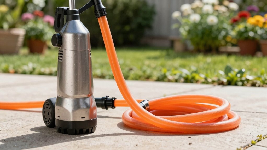
Because the fluid’s volumetric flow rate stays the same through a nozzle, any reduction in cross‑sectional area must be matched by an increase in velocity, as dictated by the continuity equation \(A_1v_1=A_2v_2\). You observe that the constant \(Q\) forces a direct inverse relationship between area and speed, so a smaller exit area yields a larger \(v_2\). This flow acceleration follows from volumetric conservation: \(Q=A v\) remains unchanged, and the density of an incompressible fluid cancels, leaving only geometric factors. In practice, a garden‑hose constriction illustrates the principle—halving the area doubles the exit velocity. The continuity equation thus predicts the exact speedup without invoking pressure changes, providing a reliable basis for nozzle sizing and performance analysis. The mass flow rate remains constant throughout the pipe. The sprinkler pattern can be adjusted by changing the nozzle geometry, which alters the exit area and thus the spray distance. Properly selecting a nozzle also determines the nozzle inches per hour needed for desired coverage.
High‑Pressure Applications: Water‑Jet Nozzles and Jet Engines
High‑pressure water‑jet nozzles and jet‑engine combustors both rely on converting stored pressure into kinetic energy, yet they do it on very different scales and with distinct design constraints. In water‑jet systems you raise inlet pressure from 60 ksi to 90 ksi by enlarging motor power and shrinking the orifice, which tightens nozzle pressure flow dynamics and forces a thinner, faster stream. The hydraulic horsepower equals pressure times flow rate, so a smaller orifice reduces flow and limits horsepower at the nozzle, despite higher velocity. Pumping system requirements jump from 100 A to 200 A for 90 ksi, demanding larger 480 V three‑phase supplies. Jet engines, by contrast, compress air in compressors, then expand it through turbine nozzles; the pressure‑to‑velocity conversion occurs at much higher temperatures and speeds, but the underlying principle—using a nozzle to translate pressure into kinetic energy—remains identical. The turbo nozzle’s pulsating action enhances cleaning efficiency by chiseling away dirt more effectively. Selecting a nozzle that matches the spray pattern of the fluid can further improve uniformity and reduce waste. Choosing a hose with a pressure rating that matches the washer’s output prevents premature failure and ensures safe operation. Understanding nozzle diameter impact on flow rate helps optimize performance across applications.

【Note】This jet nozzle must be paired with a power washer to deliver powerful water pressure. If used independently, it will only output standard water pressure.
4 PRECISION TIPS INCLUDED: Comes with Jet Stream (Red), Triple Blast (Purple), Flat Spray (Black), and Wide Stream (White) for targeted cleaning, light sweeping, and gentle watering

HEAVY-DUTY & PREMIUM BRASS MATERIAL: Our set includes 2pcs brass hose shut off valve with brass handles & 2pcs brass hose jet nozzles. The solid brass material ensures durability and longevity, while the rugged design allows it to withstand accidental drops and bumps. Extremely durable and resistant to rust. You can use it for extended periods without worrying about wear and tear, and it can withstand high water pressure without cracking or leaking.
Designing Nozzles for Desired Pressure‑Velocity Trade‑offs
Designing a nozzle to hit a specific pressure‑velocity target starts with recognizing that bore size dictates the trade‑off: a smaller throat accelerates the flow but drains static pressure, while a larger throat preserves pressure at the expense of speed. You evaluate the inverse relationship: a 4 mm bore yields 423 % higher exit velocity but 96 % lower pressure, whereas a 9 mm bore maintains pressure with modest velocity. A 6 mm throat offers a compromise—128 % velocity gain and only 81 % pressure loss versus the smallest size. Apply Bernoulli’s principle and continuity to predict kinetic‑energy conversion, then select optimum nozzle materials that resist erosion at high velocities. Integrate nozzle cooling strategies to manage thermal loads, ensuring material integrity while achieving the desired pressure‑velocity balance. The energy balance equation shows that when heat transfer and work are negligible, the exit velocity can be directly related to the enthalpy drop. Maintaining steady uniform flow requires careful geometry to minimize turbulence and keep pressure consistent throughout the nozzle. Understanding surface roughness effects helps predict additional pressure loss due to friction within the nozzle passage.

High Flow for Ultra-Fast Printing: Enlarged nozzle chamber delivers a max flow rate of 30 mm³/s, enabling high-speed printing at up to 600 mm/s without sacrificing precision – ideal for reducing print time on large models.

Precise Machine Compatibility: Compatibility with Anycubic Kobra S1 Max Combo 3D printer to ensure a secure flush fit and optimal mechanical integration within the factory print head assembly
Precise Machine Compatibility: Compatibility with Anycubic Kobra S1 Max Combo 3D printer to ensure a secure flush fit and optimal mechanical integration within the factory print head assembly
Fire‑fighting Nozzle Pressure: Reach, Impact, and Reaction
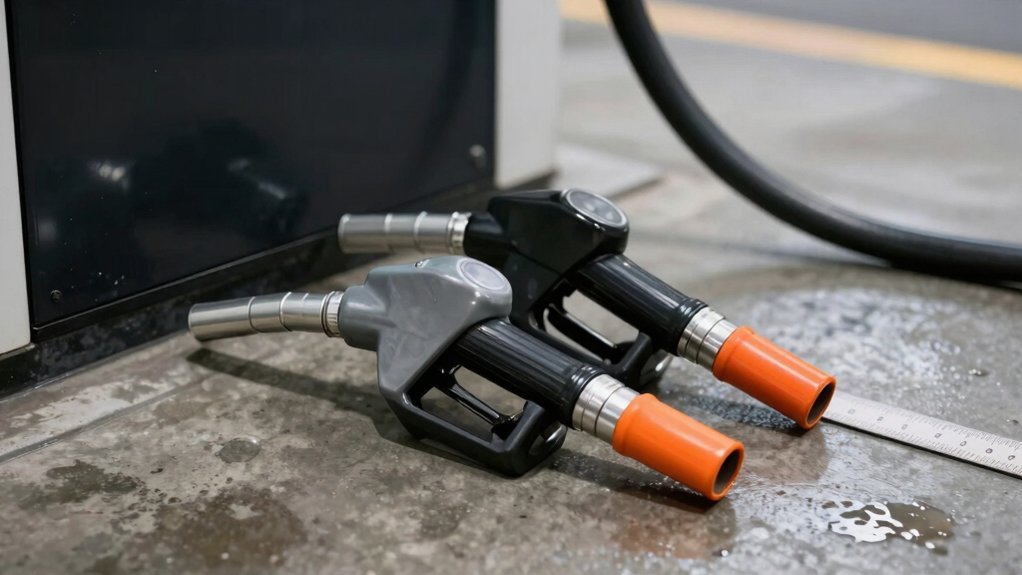
When you set a firefighting nozzle to 50 psi, you get a solid‑bore stream that balances reach, impact, and reaction: a 1¼‑inch tip throws 415 gpm up to 86 ft, while a 7/8‑inch tip at the same pressure delivers 161 gpm with roughly 60 lb of pushback. At 50 psi, smooth‑bore tips maintain a predictable flow rate, so a 1 1/8‑inch or 1¼‑inch tip reaches about 70 ft, whereas 7/8‑inch and 15/16‑inch tips hit 60 ft. Impact depends on momentum transfer; a 180 gpm attack line requires significant physical effort, but lower pressure preserves impact while cutting reaction force. Reaction force equals jet momentum, giving 60 lb for a 7/8‑inch tip and 69 lb for a 15/16‑inch tip, both comfortable for single‑firefighter operation. Selecting the proper nozzle type is essential for achieving the desired flow capacity. When the downstream pressure falls below a critical value, the flow can become choked flow, causing the mass flow rate to plateau despite further increases in upstream pressure. Understanding the differences between spray pattern types helps you match the nozzle to the cleaning task for optimal performance and safety. Properly sizing the nozzle also ensures the system stays within the recommended pressure range for safe operation.
Why Pressure Drops at the Nozzle Exit – Debunking the Myth
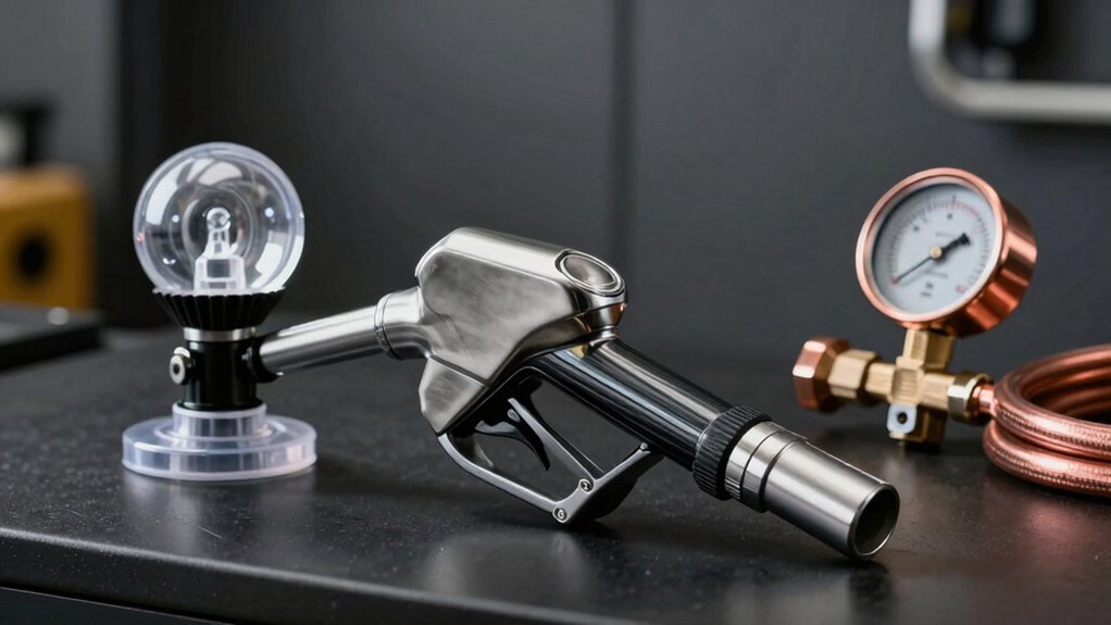
Even though a firefighting nozzle can throw a high‑velocity stream, the pressure you read at the tip is always lower than the pressure supplied to the inlet. The drop occurs because static pressure is converted into kinetic energy as fluid accelerates through the converging section. The pressure gradient required to push fluid toward the exit forces the static pressure down, while the velocity head rises according to Δp = ½ ρ V². At optimum exit conditions the exit pressure matches atmospheric (back) pressure, maximizing thrust without adding static pressure. Downstream flow dynamics then recover some kinetic energy as the jet mixes with ambient fluid, but the net static pressure at the nozzle plane remains lower than the inlet. This explains why the myth of a pressure boost at the exit is incorrect. The maximum thrust condition occurs when the exit pressure equals atmospheric pressure. This principle is the same in steam turbines, where thermal‑to‑kinetic conversion drives the rotor blades. The flow rate is also limited by pipe size and system resistance, which together determine the achievable pressure at the nozzle. Selecting the proper nozzle type based on spray pattern ensures efficient water distribution and minimizes pressure loss.
Pressure‑Increase Checklist: When a Nozzle Boosts Pressure and When It Doesn’t
If you keep the flow rate constant, a smaller nozzle will raise the static pressure at the inlet because the restriction forces the pump to work harder, but the pressure at the exit will still drop as the fluid accelerates through the converging section. Use this checklist: 1) Verify the pump’s rated flow (gpm) and guarantee the nozzle’s orifice matches that flow; a tighter orifice increases inlet pressure on pressure pumps. 2) Confirm the nozzle is not undersized enough to over‑pressurize the pump, which can cause premature wear. 3) Check that the discharge pressure aligns with the desired dispersion patterns; higher inlet pressure improves pattern cohesion. 4) If the nozzle is oversized, expect lower inlet pressure and weaker dispersion. 5) Apply Bernoulli’s principle to predict exit pressure drop regardless of inlet gain. The friction loss in longer hoses can further reduce the pressure delivered to the nozzle.